
Cellular localization unit, array, and device and formation method of cellular localization unit, array, and device

A cell positioning and array technology, applied in the field of cell detection, can solve the problem that there is no guarantee that there is only one single cell, and achieve the effect of improving positioning accuracy and throughput, and high-sensitivity positioning

Inactive Publication Date: 2015-07-22
苏州龙达生物科技有限公司
View PDF7 Cites 6 Cited by
  • Summary
  • Abstract
  • Description
  • Claims
  • Application Information

AI Technical Summary

Problems solved by technology

[0006] Using pDEP to locate cells and attract cells to the microelectrode has a strong positioning effect. However, since pDEP will be applied to all cells that are close to the electrode at the same time, they will all be attracted to the surface of the electrode, and it is impossible to ensure that each positioning electrode Or there is only one single cell on the electrode group, so it also has certain limitations

Method used


Image

  • Cellular localization unit, array, and device and formation method of cellular localization unit, array, and device
  • Cellular localization unit, array, and device and formation method of cellular localization unit, array, and device
  • Cellular localization unit, array, and device and formation method of cellular localization unit, array, and device

Examples


Embodiment 1

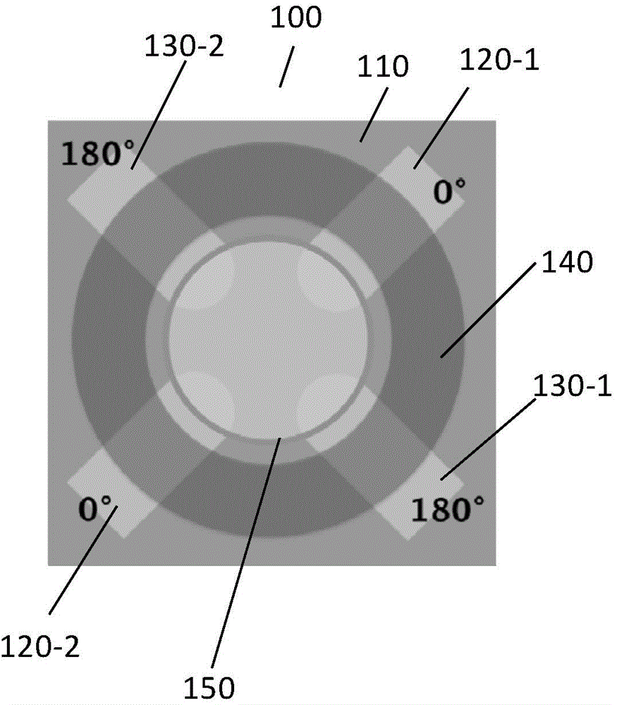
[0042] refer to figure 1 As shown, in this embodiment, a strip-shaped microelectrode is used, and the ends of the microelectrodes of the strip are arranged opposite to each other, and the maximum electric field intensity is formed in the area surrounded by the ends, so that the cells are positioned here.

[0043] In a specific embodiment, the microelectrodes are formed on the substrate 110, and there are two pairs of microelectrodes, that is, four, the first microelectrode 120-1, the second microelectrode 120-2, the third microelectrode 130-1 and The fourth microelectrode 130-2, these microelectrodes are strip-shaped, evenly distributed on a circle, the ends of each pair of microelectrodes 120-1, 120-2 are all arranged oppositely, the interval between the opposite ends Can be smaller than the size of the cells to be tested for better positioning of the cells. In this embodiment, the number of microelectrodes is two pairs, which is only an example here, and in other embodiment...

Embodiment 2

[0059] refer to Figure 6 As shown, in this embodiment, a ring-shaped microelectrode is used, and the ring-shaped micro-electrode is arranged concentrically, and the maximum electric field intensity is formed in the ring-shaped micro-electrode, so that the cells are positioned here.

[0060] In a specific embodiment, the microelectrode is formed on the substrate 210, and the microelectrode is a pair of concentrically arranged annular microelectrodes 220-1, 220-2, wherein the diameter of the inner ring microelectrode 220-1 is 2mm. -50um, the width is 2-20um, the diameter of the outer ring microelectrode 220-2 is 5-100um, the width is 2-20um, and the distance between the inner and outer microelectrodes is 2-20um. The leading end of the inner ring microelectrode 220 - 1 is located above the outer ring microelectrode 220 - 2 , and is separated by an isolation layer 230 between them.

[0061] Same as embodiment 1, a cell positioning hole (not shown) is also formed on the microelec...


PUM

PropertyMeasurementUnit
thicknessaaaaaaaaaa
widthaaaaaaaaaa

Abstract

The invention provides a cellular localization unit, array and device and a formation method of the cellular localization unit, array and device. The cellular localization unit comprises a substrate and a cellular localization hole. At least one pair of microelectrodes is arranged on the substrate; the microelectrodes are separated and each pair of the electrodes is symmetrically dispersed relatively to the same point to generate a normal dielectrophoretic force area at an area where the ends of the microelectrodes gather; and voltage signals connected to adjacent microelectrodes have opposite phases. The cellular localization hole is located above the microelectrodes; the accommodation room of the cellular localization hole exposes the normal dielectrophoretic force area; and the accommodation room is for a single cell. AC signals with certain amplitudes, frequencies and phases are applied to the microelectrodes, so that cells move towards the surfaces of the microelectrodes, and the cellular localization hole matches the microelectrodes to allow a single cell to be accurately localized at a certain position.

Description

technical field [0001] The invention relates to the technical field of cell detection, in particular to a cell positioning unit, an array, a device and a forming method thereof. Background technique [0002] Cells are the basic unit of life activities. In the fields of life science and medicine, cells need to be analyzed and studied. The manipulation and analysis of single cells is one of the current research directions. [0003] Microfluidic chip (Microfluidic chip) developed on the basis of Micro-Electro-Mechanical Systems (MEMS) technology, due to its advantages of small size, high integration and fast response, it is widely used in cell manipulation and detection. The field has been widely used to manipulate, transport and respond to cell populations or single cells. [0004] In addition, the application of dielectrophoresis technology (Dielectrophoresis, DEP) to the manipulation, separation and detection of cells is also one of the research hotspots. Dielectrophoresis...

Claims


Application Information

Patent Timeline
Patent Type & Authority Applications(China)
IPC IPC(8): C12M1/00C12M1/42
CPCB03C5/00C12M1/42G01N33/4836B03C5/005B03C5/022G01N27/44791G01N33/48728
Inventor 黄成军罗军赵超
Owner 苏州龙达生物科技有限公司
Learn More