Magnetic force type force limiting device

A magnetic force and magnet technology, applied in the field of tension protection devices, can solve problems such as endangering personal safety and prone to accidents, and achieve the effect of ensuring safety

Inactive Publication Date: 2015-07-22
何少敦
View PDF6 Cites 2 Cited by
  • Summary
  • Abstract
  • Description
  • Claims
  • Application Information

AI Technical Summary

Problems solved by technology

[0004] In order to solve the problem that the operation or stop of the driving device in the current traction equipment is controlled by electrical switches or electronic components. When electrical switches or electronic components fail, or manual operation errors are easy to cause accidents, which will endanger personal safety. , the present invention proposes a magnetic force limiting device, which consists of two tension parts magnetically attracting each other to form a tension connection assembly, and force points are set at both ends of the tension connection assembly, and the tension connection assembly is implemented through the force point. Pulling force, when the pulling force reaches the magnetic force, the pulling force connection components are separated to release the pulling force, and finally play a protective role

Method used


Image

  • Magnetic force type force limiting device
  • Magnetic force type force limiting device
  • Magnetic force type force limiting device

Examples


Embodiment Construction

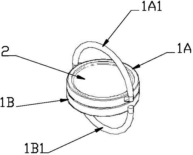
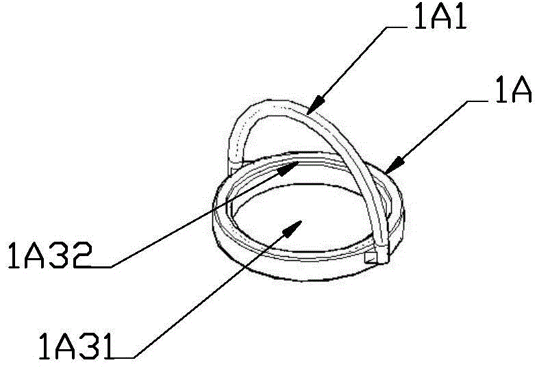
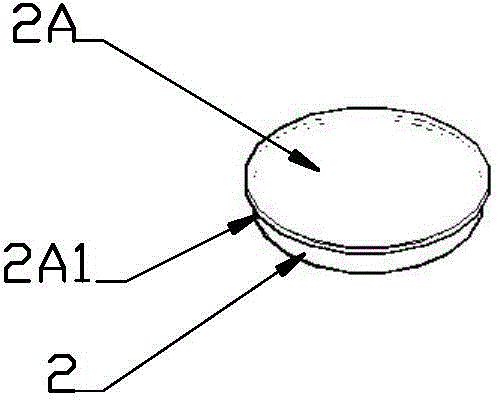
[0034] figure 1 , figure 2 , image 3 , Figure 4 It is a structural schematic diagram of the first embodiment of the present invention. in, figure 1 for the general picture, figure 2 , image 3 , Figure 4 It is a schematic diagram of the local structure.

[0035]As shown in the figure, in this example, the magnetic force limiting device includes a first tension member 1A and a second tension member 1B, and the first tension member 1A and the second tension member 1B are respectively provided with force points, and the force points are used to The tension connection assembly implements tension, and when the external tension reaches the suction force between the first tension piece 1A and the second tension piece 1B, the tension connection assembly formed by the suction of the first tension piece 1A and the second tension piece 1B is closed. separate to release the tension.

[0036] In this example, the first tension member 1A is a shell-like structure and a magneti...


PUM


Abstract

Disclosed is a magnetic force limiter, for solving the problem that, in current traction devices, the running or stopping of a driving device is controlled by an electrical switch or an electronic component, wherein when the electrical switch or the electronic component fails, or when a manual operation error occurs, accidents may easily happen, thus endangering personal safety. Provided is a magnetic force limiter, wherein two tension members (1Α, 1Β) are magnetically attracted to each other, thereby together constituting a tension connection assembly, and force bearing points for applying tension to the tension connection assembly are arranged at both ends of the tension connection assembly. When the tension achieves the magnetic suction-combining force, the tension connection assembly is separated, thereby releasing the tension, and ultimately playing a protective role. Since no electronic component is needed, it will not produce uncontrolled situations, and thus can effectively ensure safety.

Description

technical field [0001] The invention relates to a tension protection device, in particular to a magnetic force limiting device. Background technique [0002] In today's medical equipment field, it is usually necessary to use electric traction equipment to treat patients with cervical or lumbar diseases. When using the current seated cervical stretch chair or horizontal stretch bed, a pull belt device is required Fix the head or waist of the human body. When the electric device is working, the pull belt device will generate a pulling force on the human body to play a pulling role. During use, for safety reasons, the user usually operates the device to control the magnitude of the traction force; or by setting the traction force of the electric device, the electric device automatically stops running when the pull force reaches the set value. For the sake of safety, some electric traction equipments now have an emergency retreat key set on the controller. When the pulling forc...

Claims


Application Information

Patent Timeline
Patent Type & Authority Applications(China)
IPC IPC(8): A61F5/045A61H1/02
CPCA63B21/4035A63B71/0054A63B2071/0072A63B2209/08
Inventor 何少敦
Owner 何少敦
Why Eureka
Try Eureka