
Ultrasonic knife bar assembly, ultrasonic knife thereof and ultrasonic knife control system

A technology of ultrasonic knife and components, which is applied in the field of medical equipment, can solve the problems of knife head wear, long-term no-load, high labor intensity, etc., and achieve the effects of accurate energy output, prolonging service life, and reducing labor intensity

Active Publication Date: 2015-07-22
MICONVEY TECH CO LTD
View PDF5 Cites 17 Cited by
  • Summary
  • Abstract
  • Description
  • Claims
  • Application Information

AI Technical Summary

Problems solved by technology

[0003] In the application of the ultrasonic scalpel, the effect of hemostasis and cutting depends on the high-frequency reciprocating movement of the cutter head, and the pressure exerted on the tissue in the jaw is an important factor affecting its cutting speed and hemostasis effect, and the jaws constitute one of them. One side is made of plastic material. If the tissue is cut and continues to be cut, the plastic spacer will be worn. After the wear reaches a certain level, the gap between the jaws will be gradually changed until the spacer is exhausted and the instrument cannot continue. use
With the existing ultrasonic scalpel, the doctor must always concentrate on observing the cutting situation of the cutter head when using it, so that the doctor cannot be distracted, and the labor intensity is high; and through the observation with the naked eye, it is impossible to accurately judge whether the tissue has been cut. Judging by experience, it is prone to long-term no-load situations, which will lead to serious wear of the cutter head and reduce the service life

Method used


Image

  • Ultrasonic knife bar assembly, ultrasonic knife thereof and ultrasonic knife control system
  • Ultrasonic knife bar assembly, ultrasonic knife thereof and ultrasonic knife control system
  • Ultrasonic knife bar assembly, ultrasonic knife thereof and ultrasonic knife control system

Examples


Embodiment 1

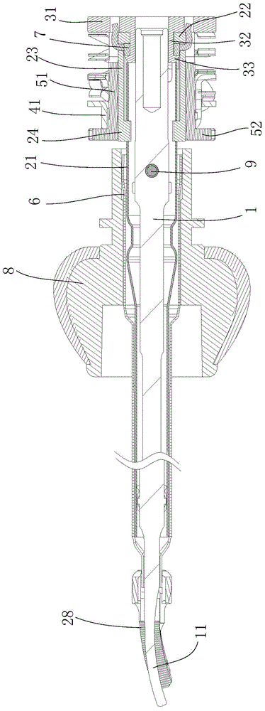
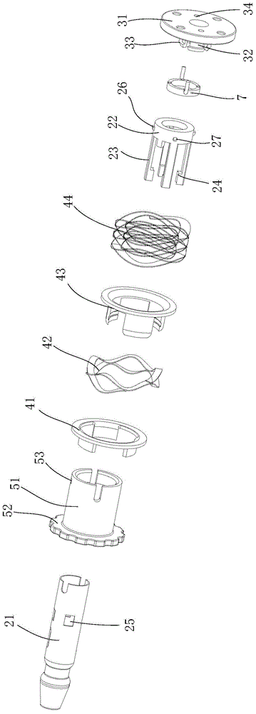
[0055] like figure 1 and figure 2 As shown, the present invention provides a kind of ultrasonic knife bar assembly, comprises the force transmission mechanism that is connected with the first half shear head 28 and is provided with the ultrasonic action rod 1 of the second half shear head 11, the first half shear head 28 and the second half shear head 28 The two halves of the cutting head 11 cooperate to form the jaw of the cutter head, and also include a pressure transmission component for receiving external toggle pressure and applying it to the force transmission mechanism, and a pressure detection element 7 is arranged between the pressure transmission component and the force transmission mechanism .

[0056]In this example, the force transmission mechanism includes an inner sleeve 21 and a connector connected to the rear of the inner sleeve 21. The inner sleeve 21 is set outside the ultrasonic action rod 1. The inner sleeve 21 is covered with an outer sleeve 6, and the ...


PUM


Abstract

The invention provides an ultrasonic knife bar assembly, an ultrasonic knife thereof and an ultrasonic knife control system. The ultrasonic knife control system comprises an ultrasonic knife control host, a prompt device, a force transferring mechanism, an ultrasonic actuating rod and a pressure transferring assembly, wherein a first half shear head is connected to the force transferring mechanism; the ultrasonic actuating rod is provided with a second half shear head; the pressure transferring assembly is used for receiving external shifting pressure and applying the external shifting pressure to the force transferring mechanism; a pressure detecting element is arranged between the pressure transferring assembly and the force transferring mechanism; the pressure detecting element and the prompt device are in communication connection with the ultrasonic knife control host; the prompt device is arranged on the ultrasonic knife control host. By adopting the ultrasonic knife bar assembly, the ultrasonic knife thereof and the ultrasonic knife control system, a doctor can know the pressure at jaws of a shear in real time; when the pressure reaches an idle pressure value, the doctor can be prompted to loosen the jaws in time; abrasion to a plastic spacer due to continuous cutting is avoided, and the service life of an instrument is prolonged; compared with the traditional visual observation method, whether tissue is cut completely can be judged more accurately; meanwhile, vigor of the doctor is released, and the burden of the doctor is relieved.

Description

technical field [0001] The invention relates to the technical field of medical instruments, in particular to an ultrasonic scalpel bar assembly, an ultrasonic scalpel, and a control system for the ultrasonic scalpel. Background technique [0002] The ultrasonic knife is an ultrasonic wave that can cut the internal tissues of the human body like a real knife by using the principle of ultrasound. The ultrasonic knife is mainly composed of the host, the drive handle and connection, the knife head and the foot switch; its working principle is to use the pedal or the hand-held knife head to activate the work. At this time, the host outputs the electric energy at the resonant frequency of the vibration system to the drive handle. , the drive handle converts electrical energy into mechanical energy and outputs it to the cutter head. The cutter head further amplifies this vibration to perform mechanical vibration, so that the water in the tissue cells is vaporized, the hydrogen bond...

Claims


Application Information

Patent Timeline
Patent Type & Authority Applications(China)
IPC IPC(8): A61B17/32
CPCA61B17/320068A61B2017/320078
Inventor 罗湖斌刘子贤刘建军孔泽明
Owner MICONVEY TECH CO LTD
Learn More