Detector device with Z-axis focus tracing and correction capacity and application method thereof

A detector and Z-axis technology, applied in the field of medical imaging, can solve problems such as high cost, and achieve the effects of low manufacturing cost, simple control, and reduced gain variation

Active Publication Date: 2015-07-22
FMI MEDICAL SYST CO LTD
View PDF6 Cites 11 Cited by
  • Summary
  • Abstract
  • Description
  • Claims
  • Application Information

AI Technical Summary

Problems solved by technology

This requires the use of complex hardware and is undoubtedly expensive

Method used


Image

  • Detector device with Z-axis focus tracing and correction capacity and application method thereof
  • Detector device with Z-axis focus tracing and correction capacity and application method thereof
  • Detector device with Z-axis focus tracing and correction capacity and application method thereof

Examples


Embodiment Construction

[0024] In order to make the technical problems, technical solutions and beneficial effects to be solved by the present invention clearer, the present invention will be further described in detail below in conjunction with the accompanying drawings and embodiments. It should be understood that the specific embodiments described here are only used to explain the present invention, not to limit the present invention.

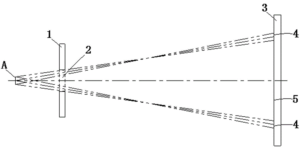
[0025] Please refer to figure 1 As shown, the X-ray emitted from the focal point A of the CT tube passes through the collimation hole 2 of the front collimator 1 and then projects onto the detector 3. The result of the X-ray projected on the detector 3 is divided into a penumbra 4 and umbra 5. The penumbra 4 is located on the periphery of the umbra 5 . The X-ray dose in the penumbra 4 is less and weaker than that in the umbra 5 . The umbra region 5 can generate a false-free image, and its image quality is clearer and more complete than that of the penumbra regio...


PUM


Abstract

The invention relates to a detector device with Z-axis focus tracing and correction capacity and an application method thereof. The detector device comprises an X ray emission source, a front collimator and a detector, collimation holes are formed in the front collimator, the front collimator is further provided with tracing holes, X rays can pass through the tracing holes, the tracing holes are symmetrical about the symmetric lines of the collimation holes, and the side faces of the tracing holes are communicated with the side faces of the collimation holes. The detector is mainly divided into an ideal attention channel region, an upper reference channel region, a lower reference channel region and a baseline channel region, the ideal attention channel region receives X rays passing through the collimation holes, the lower reference channel region is located on the lower side of the baseline channel region, and the upper reference channel region, the lower reference channel region and the baseline channel region are used for receiving X rays passing through the tracing holes. According to the detector device and the application method thereof, Z-axis focus tracing and correction are conducted more simply and conveniently, cost is effectively reduced, and economic benefits are increased.

Description

technical field [0001] The invention mainly belongs to the technical field of medical imaging, and in particular relates to a detector device with Z-axis focus tracking and correction capabilities and a use method thereof. Background technique [0002] Digital imaging systems can be used to take images to help doctors make a correct diagnosis. A digital radiography imaging system typically includes a source and a detector. Energy generated by a source, such as X-rays, passes through the object to be imaged and is detected by a detector. An associated control system acquires image data from the detector and modulates a corresponding diagnostic image on the display. One or more collimators may be used to block and / or confine X-rays or other energy from the detector. For example, an opening may be provided in the collimator through which X-rays pass from the source to the detector. [0003] The CT detector system uses the aforementioned principles to work. At present, th...

Claims


Application Information

Patent Timeline
Patent Type & Authority Applications(China)
IPC IPC(8): A61B6/00
Inventor 阿泽子·伊赫莱夫
Owner FMI MEDICAL SYST CO LTD
Why Eureka
Try Eureka