
Bent optical waveguide

A waveguide and bending technology, applied in the field of optics and photonics, which can solve the problem of large bending radius and achieve the effect of reducing the size

Active Publication Date: 2015-07-15
VTT OY TECH RES CENT
View PDF8 Cites 18 Cited by
  • Summary
  • Abstract
  • Description
  • Claims
  • Application Information

AI Technical Summary

Problems solved by technology

However, the obtained bend radii are still quite large, in fact, for example, two orders of magnitude larger than the waveguide width, and in particular the manufacture of waveguides is challenging due to very tight tolerance requirements

Method used


Image

  • Bent optical waveguide
  • Bent optical waveguide
  • Bent optical waveguide

Examples


Embodiment Construction

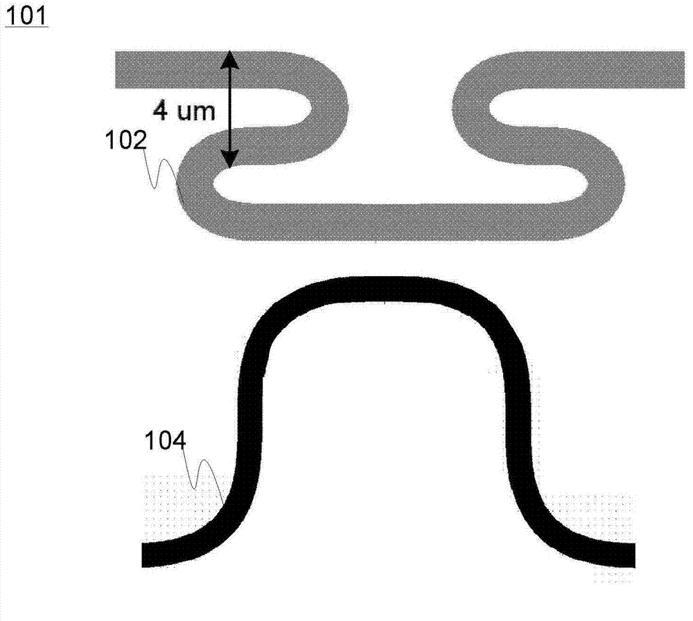
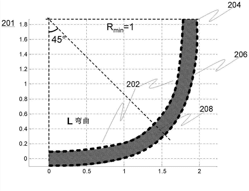
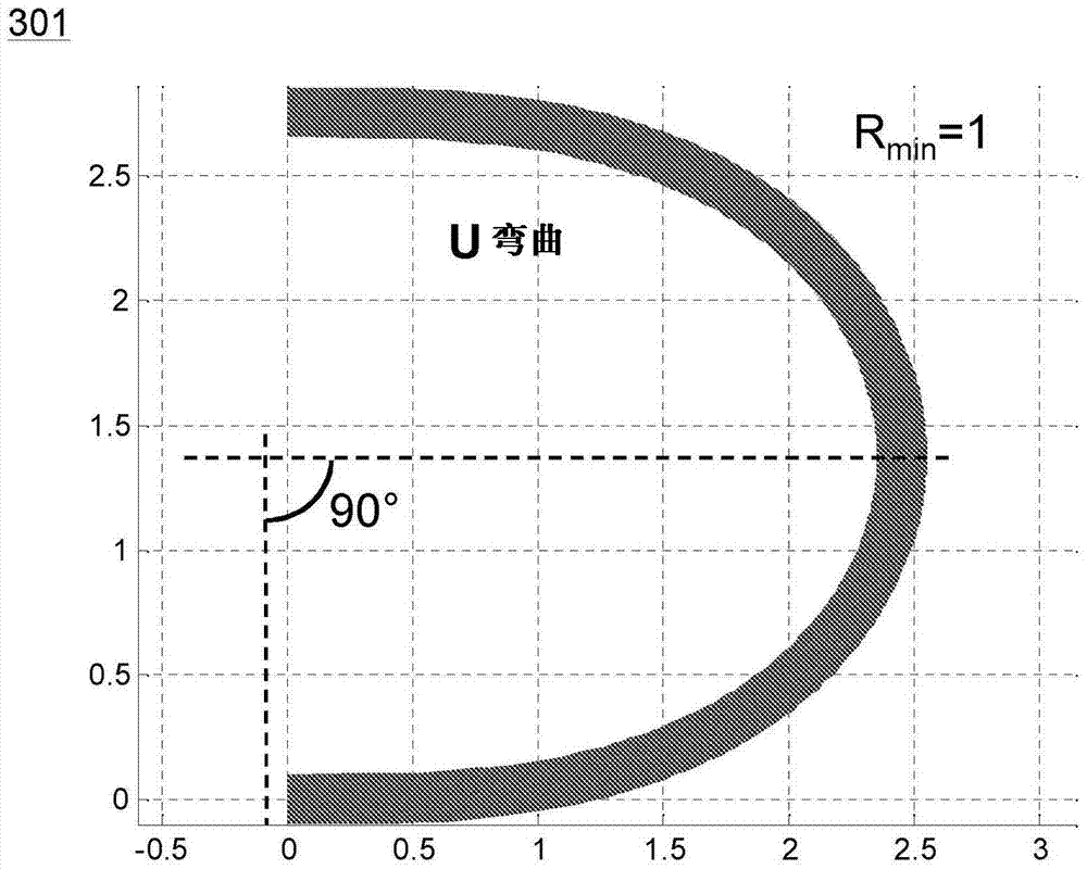
[0047] exist figure 1 At 101 , by way of example only, at 102 and 104 two different embodiments of the invention are generally shown. Bends such as 'U' bends, 'S' bends, 'L' bends and virtually any degree of curvature desired can be made. Different basic bend shapes can be cleverly combined to build more complex bends and bends can be designed using (mirror / point) symmetry.

[0048] For example, two 'U' bends can be combined to form an 'S' bend, and the 'U' bend itself can be constructed from two mirror-symmetrical halves, i.e. a doubly symmetrical structure can be created. However, those skilled in the art will understand that such symmetry is not necessary to create a bend using the present invention, ie the bend segments before and after the point of maximum curvature of the bend are not necessarily mirror symmetric.

[0049] The resulting bend is optimized to be optically efficient and provides a small footprint, as well as a small, non-constant bend radius. The order o...


PUM


Abstract

An optical multi-mode HIC (high index contrast) waveguide (102,104, 201, 301) for transporting electromagnetic radiation in the optical waveband, the waveguide comprising a guiding core portion (204) with higher refractive index, and cladding portion (206) with substantially lower refractive index configured to at least partially surround the light guiding core in the transverse direction to facilitate confining the propagating radiation within the core, the waveguide being configured to support multiple optical modes of the propagating radiation, wherein the waveguide incorporates a bent waveguide section (202) having bend curvature that is configured to at least gradually, preferably substantially continuously, increase towards a maximum curvature of said section from a section end.

Description

technical field [0001] Generally, the present invention relates to optics and photonics. In particular, but not exclusively, the invention relates to HIC (High Index Contrast) optical multimode waveguides and their bending. Background technique [0002] Optical waveguides, including multimode dielectric waveguides, are designed to transmit electromagnetic waves in the optical band. An optical waveguide is basically a light pipe configured by proper choice of core and surrounding cladding materials with higher and lower refractive indices respectively to confine light to travel therein without leaking it into the environment. [0003] Optical waveguides can be defined according to their geometry (slab (planar) or ribbon, cylinder, etc.), mode structure (single-mode, multi-mode), refractive index profile (step or gradient index), and, for example, materials (glass, polymers, semiconductors, etc.). The refraction of light at the core / cladding interface is generally governed ...

Claims


Application Information

Patent Timeline
Patent Type & Authority Applications(China)
IPC IPC(8): G02B6/125G02B6/122
CPCG02B6/125G02B6/122G02B6/1223G02B6/02047G02B6/262
Inventor 马特奥·凯尔基蒂莫·阿尔托
Owner VTT OY TECH RES CENT
Learn More