Calibration device and method for g-clip

A technology of correction device and correction rod, which is applied in clamps, manufacturing tools, etc., can solve the problems of high labor intensity for workers, short length of correction axis, troublesome operation, etc., and achieve the effect of short length, fast correction and reduced labor intensity

Active Publication Date: 2016-09-07
ZHEJIANG GUANGHUI TOOLS
View PDF7 Cites 0 Cited by
  • Summary
  • Abstract
  • Description
  • Claims
  • Application Information

AI Technical Summary

Problems solved by technology

[0006] The present invention solves the defects of troublesome operation and low efficiency in existing micro-calibration using a standard screw for calibration, and provides a calibration device and calibration method for a G-shaped clip, which uses a calibration axis capable of emitting infrared rays for calibration, which is easy to operate and easy to calibrate. fast
[0007] The present invention also solves the defect that the existing micro-calibration uses a standard screw for calibration, and the calibration result cannot avoid the deformation of the standard screw, and errors occur in the calibration, and provides a calibration device and calibration method for a G-shaped clamp, which adopts a device capable of emitting infrared rays The proofreading shaft is used for proofreading. The length of the proofreading shaft is short, and there will be no deformation after repeated use. The proofreading structure is less affected by the deformation of the proofreading shaft.
[0008] The present invention also solves the defects of manual micro-calibration of G-shaped clips and high labor intensity of workers, and provides a correction device and correction method for G-shaped clips, which can be automatically corrected and corrected to reduce the labor intensity of workers

Method used


Image

  • Calibration device and method for g-clip
  • Calibration device and method for g-clip
  • Calibration device and method for g-clip

Examples


Embodiment

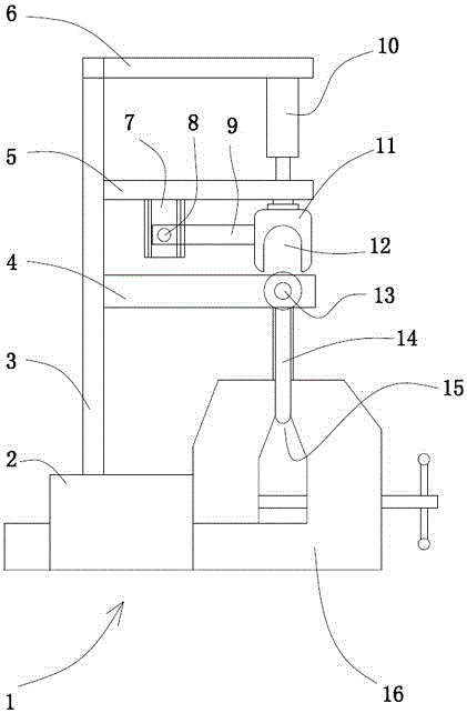
[0030] Embodiment: a kind of correction device of G type clip (see attached figure 1 ), including a clamping table 1 for clamping G-shaped clamps. The clamping table is divided into a fixed part 2 and a movable part 16. The movable part is movable relative to the fixed part. A rotating screw is arranged on the movable part. The connection between the movable part and the fixed part The clamping seam 15 of the G-shaped clip is formed between them, and the limiting device of the G-shaped clip is arranged at the clamping seam, and the position of the G-shaped clip is limited by the limiting device at the clamping seam.

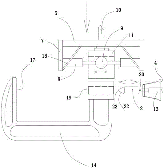
[0031] A bracket is fixed on the fixed part, and the bracket includes a vertical bar 3, a fixed horizontal bar 6 fixed on the top of the vertical bar, a proofreading shaft supporting the horizontal bar 4 fixed on the lower part of the vertical bar, and a lifter that can move up and down along the vertical bar on the vertical bar. Crossbar 5. A lifting device 10 ...


PUM


Abstract

The invention relates to a correcting device for a G-shaped clamp and a correcting method. The correcting device solves the defects of troublesome operation and low efficiency when a standard threaded rod is used for correcting in existing micro correction. The correcting device comprises a correcting shaft, a rotatable correcting rod and a control component, wherein the correcting shaft can be automatically inserted in a threaded rod hole, and an infrared transmitter is arranged inside the correcting shaft; a correcting part is arranged on the correcting rod; the control component comprises an infrared receiving component, a processing component and a driving component, the infrared receiving component is arranged at the fixed end of the G-shaped clamp and is used for receiving infrared signals, the processing component is used for processing the received infrared signals and outputting driving signals of a rotating mechanism, and the driving component is used for receiving the driving signals and controlling the rotating mechanism to work. Infrared rays can be transmitted by the correcting shaft, whether two arms of the G-shaped clamp need micro correction is judged through the projection of the infrared rays on the fixed end of the G-shaped clamp, and the correction is quick.

Description

technical field [0001] The invention relates to a correction device and a correction method of a fixture, in particular to a correction device and a correction method of a G-shaped clip, which can be corrected automatically by infrared rays. Background technique [0002] Woodworking clips are necessary tools for woodworking. They are simple in structure and dexterous to use. They are good helpers for woodworking. They are usually divided into F-type clips, G-type clips and A-type clips according to their shapes. The G-type clamp has two arms, one of which is a fixed end, and the other arm is provided with a screw hole, and a screw is screwed in the screw hole, and the workpiece can be clamped by turning the screw to adjust the distance between the screw end and the fixed end. [0003] In order to ensure the stability of the clamping and the rationality of the force, the axis of the screw should be perpendicular to the plane of the fixed end, that is to say, the axis of the s...

Claims


Application Information

Patent Timeline
Patent Type & Authority Patents(China)
IPC IPC(8): B25B5/10
CPCB25B5/10
Inventor 李光辉
Owner ZHEJIANG GUANGHUI TOOLS
Why Eureka
Try Eureka