
Centering device for plate-shaped work piece

A technology of plate-shaped workpieces and centering devices, applied in positioning devices, feeding devices, measuring devices, etc., can solve problems such as difficulty in conveying two pieces, reduced operation rate of forming presses, difficulty in speeding up, etc., to shorten calculation time , reduce supply costs, and improve versatility

Active Publication Date: 2015-07-08
HONDA MOTOR CO LTD +1
View PDF5 Cites 3 Cited by
  • Summary
  • Abstract
  • Description
  • Claims
  • Application Information

AI Technical Summary

Problems solved by technology

Reduced operating rate of forming presses
[0008] In addition, when two blanks are conveyed at the same time, the control of the claws becomes complicated, and as a result, the conveyance of two blanks becomes difficult.
[0009] The transportation and position correction of the blank can be carried out by the robot without using claws, but in this case, it takes time and cannot keep up with the cycle when there is only one robot
In order to catch up with the cycle, when two robots are installed, the mutual interference of the robots becomes a problem, the control becomes complicated, and the installation space of the robots is doubled
[0010] That is, the centering device of Patent Document 1 has the following problems: it is difficult to increase the speed and the operation rate is low, so it cannot cope with multi-sheet conveyance

Method used


Image

  • Centering device for plate-shaped work piece
  • Centering device for plate-shaped work piece
  • Centering device for plate-shaped work piece

Examples


Embodiment

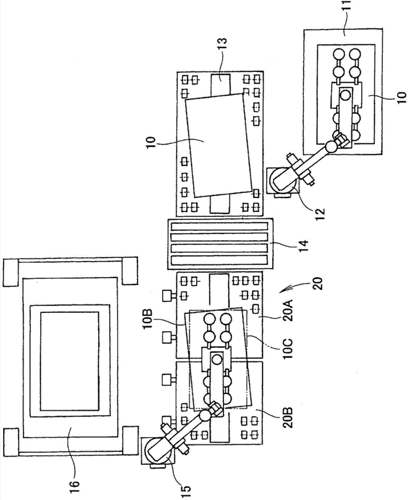
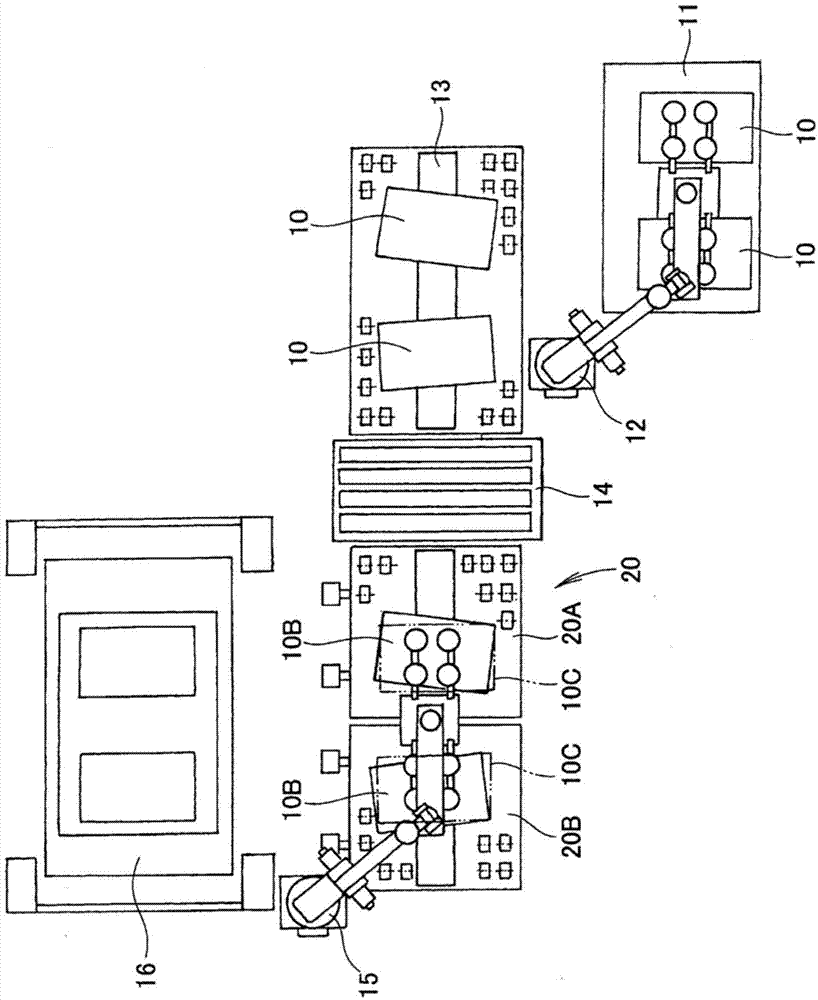
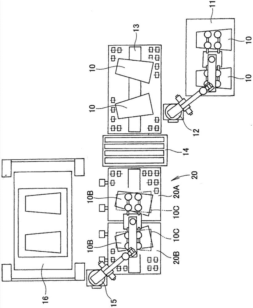
[0046] Such as figure 1 As shown, one sheet of plate-shaped workpiece 10 fed from the previous process is placed on the receiving table 11. The first robot 12 moves the plate-shaped workpiece 10 from the receiving table 11 to the entrance table 13. The plate-shaped workpiece 10 is put into the washing machine 14 from the entrance table 13 in a timely manner, and is washed. Then, the cleaned plate-shaped workpiece 10 is conveyed to the first centering device 20A and the second centering device 20B.

[0047] In this case, the plate-shaped workpiece 10 may be a vertically long material that straddles the first centering device 20A and the second centering device 20B.

[0048] Then, after cleaning, the plate-shaped workpiece before centering is denoted with reference numeral 10B, and the plate-shaped workpiece after centering is denoted with reference numeral 10C, thereby identifying the plate-shaped workpiece 10.

[0049] In addition, the first centering device 20A and the second cent...


PUM


Abstract

A centering device for a plate-shaped work piece comprises: a table (21) having a conveyor mechanism (23) for conveying a plate-shaped work piece (10) in the horizontal direction; a camera (56) for taking an image of the plate-shaped work piece (10) placed on the table (21); a table movement mechanism (28) for moving the table (21) horizontally in the direction orthogonal to the conveyance direction; a table rotation mechanism (60) for rotating the table (21) about a vertical axis; a computation unit (58) for comparing target centering position information and information acquired by the camera (56) and computing the movement amount of the conveyor mechanism (23), the movement amount of the table movement mechanism (28), and the movement amount of the table rotation mechanism (60); and a control unit (59) for controlling the conveyor mechanism (23), the table movement mechanism (28), and the table rotation mechanism (60) on the basis of the movement amounts calculated by the computation unit (58).

Description

Technical field [0001] The invention relates to a centering device for positioning a plate-shaped workpiece at a target centering position for the next process. Background technique [0002] The process of obtaining a pressure-formed product using the strip as a starting material is implemented in the following procedure. [0003] The blank is cut from the strip plate through a punch or other device. The resulting blank is transported to the vicinity of the forming press. Furthermore, the blank is fed into the forming press by the robot. The blank is pressure-formed by a forming press. [0004] The molding press has a mold for molding. The blank must be correctly placed in the forming mold. However, the blank is sometimes not in the desired position. As a countermeasure, a centering device for positioning the blank is provided. [0005] Various centering devices have been proposed in the past (for example, refer to Patent Document 1). [0006] The centering device disclosed in Pa...

Claims


Application Information

Patent Timeline
IPC IPC(8): B21D43/00G01B11/00
CPCB65H2511/20B65H2557/24B65H2511/212B21D43/105B65H2511/232B65H2553/42B65H2511/22B65H2557/23B65H2404/2693B65H9/10B65H11/002G01B11/002B65H2220/03B65H2220/02B65H2220/01B65H2220/11B65H2511/23B65H9/00
Inventor 松山真也铃木雄太西本进松本俊彦铃木雅尚玉井凉二加藤博光
Owner HONDA MOTOR CO LTD
Learn More