
A lens adjustment module and projection device

A lens module and lens technology, applied in projection devices, optics, instruments, etc., can solve the problems that the lens can only move up and down, cannot be widely used, and cannot move left and right, so as to avoid deformation or even breakage, light weight, and easy operation Effect

Active Publication Date: 2016-09-07
QISDA OPTRONICS (SUZHOU) CO LTD +1
View PDF5 Cites 0 Cited by
  • Summary
  • Abstract
  • Description
  • Claims
  • Application Information

AI Technical Summary

Problems solved by technology

The known lens adjustment mechanism usually can only be adjusted in one axis, so that the lens can only move up and down but not left and right. For left and right movement, it must be adjusted by moving the entire projector, which reduces the practicality. sex
The lens adjustment mechanism that can move the lens left and right as well as up and down is not widely used because the mechanism is too complicated, which leads to problems such as increased cost and heavy weight.

Method used


Image

  • A lens adjustment module and projection device
  • A lens adjustment module and projection device
  • A lens adjustment module and projection device

Examples


Embodiment Construction

[0027] In order to have a further understanding of the purpose, structure, features, and functions of the present invention, the following detailed descriptions are provided in conjunction with the embodiments.

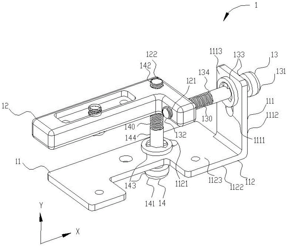
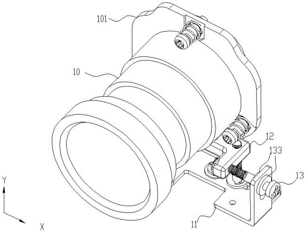
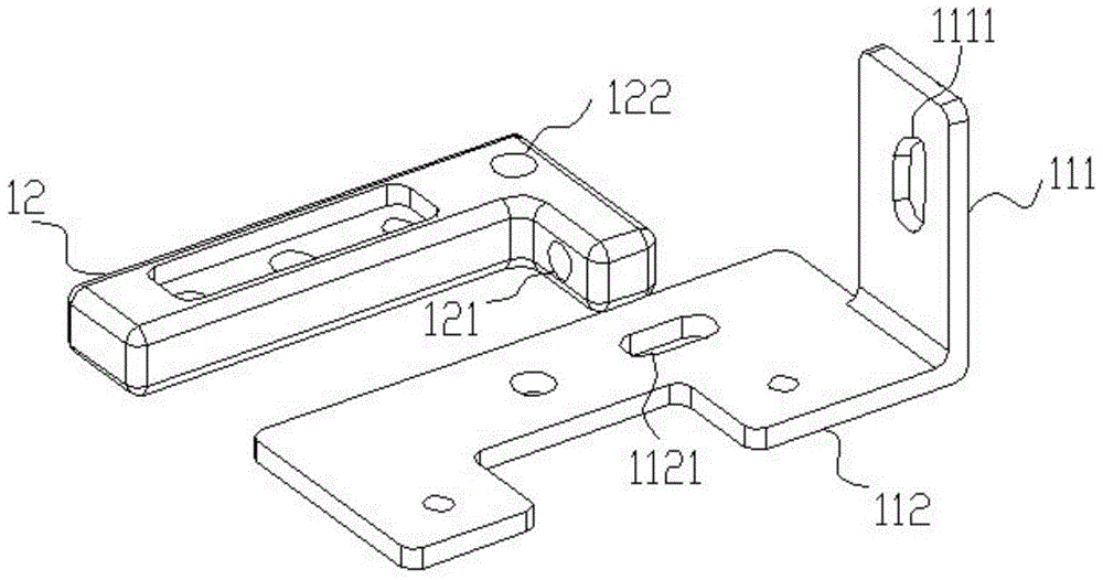
[0028] refer to Figure 1 to Figure 3 As shown, a schematic structural diagram of a lens adjustment module according to an embodiment of the present invention is disclosed. figure 1 It is a schematic structural diagram of the lens adjustment module proposed by the embodiment of the present invention, figure 2 for figure 1 The schematic diagram of the structure when the lens adjustment module is matched with the lens is shown, image 3 for figure 1 The schematic diagram of the structure of the fixed seat and the movable pivot seat shown. The lens adjustment module 1 of the present invention is used to adjust the position of the lens 10 . The lens adjustment module 1 includes a fixed base 11 , a movable pivot base 12 , a first adjustment rod 13 and a second adjustm...


PUM


Abstract

The invention discloses a lens adjustment module and a projection device. The lens adjustment module is used for adjusting the position of a lens and comprises a fixing seat, a movable pivot seat, a first adjustment rod and a second adjustment rod. The movable pivot seat is used for being fixedly connected with the lens, so that the lens moves along with the movement of the movable pivot seat. The first adjustment rod is provided with a first end and a second end which are opposite to each other, the first end is in pivot joint with the fixing seat, and the second end is in pivot joint with the movable pivot seat. The second adjustment rod is provided with a third end and a fourth end which are opposite to each other, the third end is in pivot joint with the fixing seat, and the fourth end is in pivot joint with the movable pivot seat. The first adjustment rod is used for rotating so as to drive the movable pivot seat to move in the first direction relative to the fixing seat. The second adjustment rod is used for rotating so as to drive the movable pivot seat to move in the second direction relative to the fixing seat.

Description

technical field [0001] The invention relates to a projection device, in particular to a lens adjustment module capable of two-dimensionally adjusting the position of the lens. Background technique [0002] After the general projector is set up for the first time or moved again, the lens needs to be adjusted by the lens adjustment mechanism, so as to adjust the image projected by the lens on the curtain or the place to be projected. The known lens adjustment mechanism usually can only be adjusted in one axis, so that the lens can only move up and down but not left and right. For left and right movement, it must be adjusted by moving the entire projector, which reduces the practicality. sex. However, the lens adjustment mechanism that can move the lens left and right and move up and down cannot be widely used because the mechanism is too complicated, which leads to problems such as increased cost and heavy weight. [0003] Therefore, it is necessary to design a new lens adju...

Claims


Application Information

Patent Timeline
Patent Type & Authority Patents(China)
IPC IPC(8): G03B21/14
CPCG03B21/142
Inventor 胡圣文
Owner QISDA OPTRONICS (SUZHOU) CO LTD
Learn More