
A cushioning energy-absorbing structure

An energy-absorbing structure and grid structure technology, applied in the design characteristics of springs/shock absorbers, springs, shock absorbers, etc., can solve the problems of unreasonable energy-absorbing structures, low buffering and energy-absorbing efficiency, etc., and achieve good energy absorption. characteristics, enhanced energy absorption capacity, the effect of high specific mass energy absorption

Active Publication Date: 2017-03-08
SOUTH CHINA UNIV OF TECH
View PDF8 Cites 1 Cited by
  • Summary
  • Abstract
  • Description
  • Claims
  • Application Information

AI Technical Summary

Problems solved by technology

[0003] At present, there are many kinds of traditional energy-absorbing devices, but most of them have unreasonable energy-absorbing structures and low buffering and energy-absorbing efficiency.

Method used


Image

  • A cushioning energy-absorbing structure
  • A cushioning energy-absorbing structure
  • A cushioning energy-absorbing structure

Examples


Embodiment Construction

[0022] The present invention will be described in further detail below in conjunction with specific embodiments.

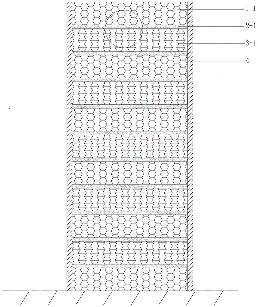
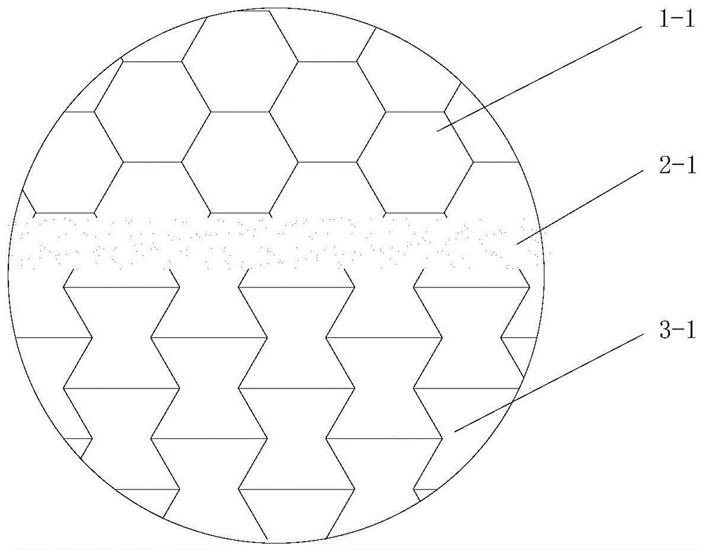
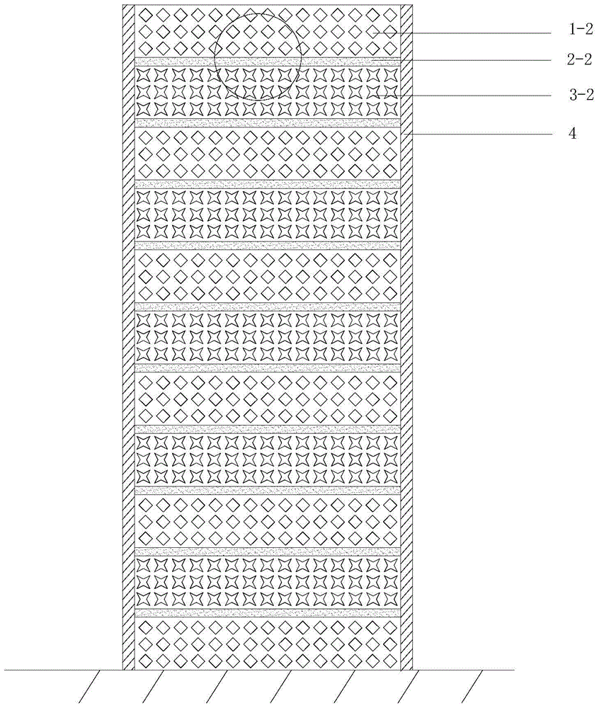
[0023] like Figures 1 to 6 shown. A buffer energy-absorbing structure of the present invention includes a shell 4, the buffer energy-absorbing structure is a multi-layer metal grid structure or porous foam structure filled in the shell 4, and the metal grid structure or porous foam structure of adjacent layers is The positive and negative Poisson's ratios are stacked alternately in the longitudinal direction.

[0024] The metal mesh structure of each layer is welded by brazing 2-1 (including the brazing between the metal mesh structure and the shell 4), and the porous foam structure of each layer is bonded by an adhesive 2-2 (including the porous foam structure and the shell 4 bonding between).

[0025] The Poisson's ratio of the metal grid structure or the porous foam structure at the collision end is positive.

[0026] The metal grid structure with a positi...


PUM

PropertyMeasurementUnit
porosityaaaaaaaaaa

Abstract

The invention discloses a buffering and energy absorbing structure. The buffering and energy absorbing structure comprises a housing. The buffering and energy absorbing structure is a multi-layer metal grid structure or porous bubble structure filled in the housing; the metal grid structures or porous bubble structures of adjacent layers are lengthways alternatively overlapped in positive and negative poisson ratio; the metal grid structure in the positive poisson ratio is composed of a three-dimensional honeycomb grid structured formed by array type regular hexagonal pore grids; the metal grid structure in the negative poisson ratio is composed of a three-dimensional stretching and expanding grid structure formed by array type concave angle pore grids; the meshes of the porous bubble structure in the positive poisson ratio are of an array type rhombus structure; the meshes of the porous bubble structure in the negative rhombus structure are of an array type four-star shaped structure. Compared with the traditional buffering and energy absorbing structure, the buffering and energy absorbing structure can effectively reduce the peak value of the impact force, so that the whole energy absorbing process is stable, and as a result, the energy absorbing efficiency of the structure can be increased.

Description

technical field [0001] The invention relates to an energy absorbing device, in particular to a buffer energy absorbing structure. Background technique [0002] Collision safety is an important indicator of the safety of various vehicles. A considerable part of the materials in the body buffer collision zone are specially designed for the purpose of car body impact resistance. Efficient impact energy absorption efficiency, lower weight and smaller load peaks are the goals pursued by the structural design of such functional parts. [0003] At present, there are many kinds of traditional energy-absorbing devices, but most of them have unreasonable energy-absorbing structures and low buffering and energy-absorbing efficiency. Contents of the invention [0004] The purpose of the present invention is to overcome the shortcomings and deficiencies of the above-mentioned prior art, provide a buffer and energy-absorbing structure, improve the deformation mode of the existing energ...

Claims


Application Information

Patent Timeline
Patent Type & Authority Patents(China)
IPC IPC(8): F16F15/04
CPCF16F1/025F16F1/371F16F2224/0225F16F2230/40
Inventor 刘旺玉林贞琼
Owner SOUTH CHINA UNIV OF TECH
Learn More