
Sand sieving method and device

A technology for screening sand and sand particles, applied in the field of sand screening methods and sand screening devices, can solve the problems of large energy consumption, clumped sand particles, unfavorable screening, etc., and achieves kinetic energy saving, good effect, and easy replacement. Effect

Inactive Publication Date: 2015-07-08
吕智林
View PDF10 Cites 8 Cited by
  • Summary
  • Abstract
  • Description
  • Claims
  • Application Information

AI Technical Summary

Problems solved by technology

In this way, sand sieving is achieved by rolling, which consumes a lot of energy, and it cannot solve the phenomenon that when the water content of sand grains is high, the sand grains will become lumpy, which is not conducive to sieving.
[0005] In short, in the existing sand screening machine, the movement of all sand particles is driven by the motor, and the reciprocating motion of the sand particles requires more kinetic energy, which requires a high-power motor

Method used


Image

  • Sand sieving method and device
  • Sand sieving method and device
  • Sand sieving method and device

Examples


Embodiment Construction

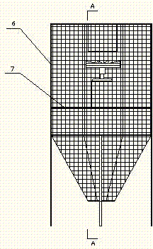
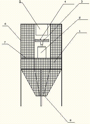
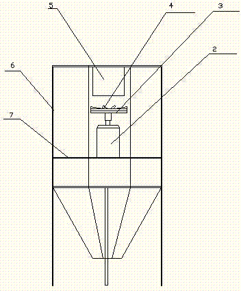
[0032] As shown in the attached figure: a sand screening device, including a filtering part and a driving part.

[0033] The filter part includes: screen 1, sand inlet 5, gravel outlet 8, support frame 6, the upper part of the support frame 6 is in the shape of a garden cylinder, and the lower part is conical, and the screen cloth 1 is fixedly attached to the support frame 6 , The sand inlet 5 is located at the upper end of the supporting frame 6, and the gravel outlet 8 is located at the lower end of the supporting frame 6.

[0034] Described driving part comprises: motor 2, impeller 3, blade 4, motor fixed frame 7, and motor 2 is fixed on the motor fixed frame 7, and impeller 3 is installed on the upper end of motor 2, and blade 4 is fixed on the impeller 3. The impeller 3 faces upwards.

[0035] The driving part is installed inside the filtering part, and the impeller 3 is located directly below the sand inlet 5 .

[0036] Motor fixing frame 7 is fixed on the middle part ...


PUM


Abstract

Disclosed are a sand sieving method and a sand sieving device. By using the sand sieving method and the sand sieving device, sand grains are transported to a rotary impeller which is rotating, the sand grains are dispersed under action of centrifugal force through rapid rotation of the rotary impeller, the dispersed sand grains touch a peripheral screen, and then a separation process of the sand grains and gravel is completed. The sand sieving device comprises a filter portion and a drive portion, wherein the filter portion comprises the screen, a sand grain inlet, a gravel outlet and a support frame, the upper portion of the support frame is in a cylinder shape, the lower portion of the support frame is in a cone shape, the screen is fixed on the support frame, the sand grain inlet is located at the upper end of the support frame, the gravel outlet is located at the lower end of the support frame, the drive portion comprises a motor, an impeller, a blade and a motor fixing frame, the motor is fixed on the motor fixing frame, the impeller is installed at the upper end of the motor, the blade is fixed on the impeller, the impeller faces upwards, the drive portion is installed in the filter portion, and the impeller is located right below the sand grain inlet. The sand sieving method and the sand sieving device fundamentally change a sand sieving viewpoint, and are good in effect.

Description

technical field [0001] The invention relates to the field of building raw material processing, in particular to a sand screening method and a sand screening device. Background technique [0002] Sand is one of the most important raw materials in the construction industry. When using sand, it is hoped that the size of the sand will be uniform, but the sand fished from the river or sand mined by other methods has different sizes, and there are also mixed sizes. The gravel needs to be screened. Generally, a sand screen machine is used to complete the sand screening process. [0003] Invention publication number: CN201110187495.X discloses a fully automatic sand screening machine, which is provided with a frame, and the frame is provided with a feeding mechanism, a sand screening mechanism and a conveying mechanism. Such a sand screening mechanism requires vibrating sand screening, and the movement space of the sand particles is very small. For the sand with water, the situatio...

Claims


Application Information

Patent Timeline
IPC IPC(8): B07B1/20B07B1/46
CPCB07B1/20B07B1/42B07B1/46
Inventor 王仁政
Owner 吕智林
Learn More