
Method for manufacturing sealing device, and sealing device

A sealing device and manufacturing method technology, applied in the direction of engine sealing, engine components, household components, etc., can solve the problem of easy to increase sliding resistance, difficulty in identifying the position of the ring-shaped convex part, and difficulty in improving the position accuracy of cutting, etc. problem, achieve the effect of reducing the effect, improving the sliding property, and suppressing the breakage

Active Publication Date: 2015-07-01
NOK CORP
View PDF8 Cites 3 Cited by
  • Summary
  • Abstract
  • Description
  • Claims
  • Application Information

AI Technical Summary

Problems solved by technology

[0004] However, when the above-mentioned cutting is performed in the case of a sealing device provided with an annular convex portion on the inner peripheral side, it is difficult to recognize the position of the annular convex portion.
Therefore, there is a problem that it is difficult to improve the accuracy of the cutting position (see Patent Document 2)
[0005] In addition, in the case of the sealing device such as the above-mentioned D ring, since the main part of the sealing device is restricted in the installation groove, it is difficult to deform, so there is also a disadvantage that the sliding resistance tends to increase.

Method used


Image

  • Method for manufacturing sealing device, and sealing device
  • Method for manufacturing sealing device, and sealing device
  • Method for manufacturing sealing device, and sealing device

Examples


Embodiment 1

[0036] refer to Figure 1 to Figure 10 The sealing device and its manufacturing method according to Example 1 of the present invention will be described. The sealing device of this embodiment can be preferably used as a hydraulic seal for reciprocating transmission systems such as AT and CVT of automobiles. In addition, it can also be used as a seal for reciprocating motion of general industrial machines such as construction machines and agricultural machines.

[0037] (Sealing means)

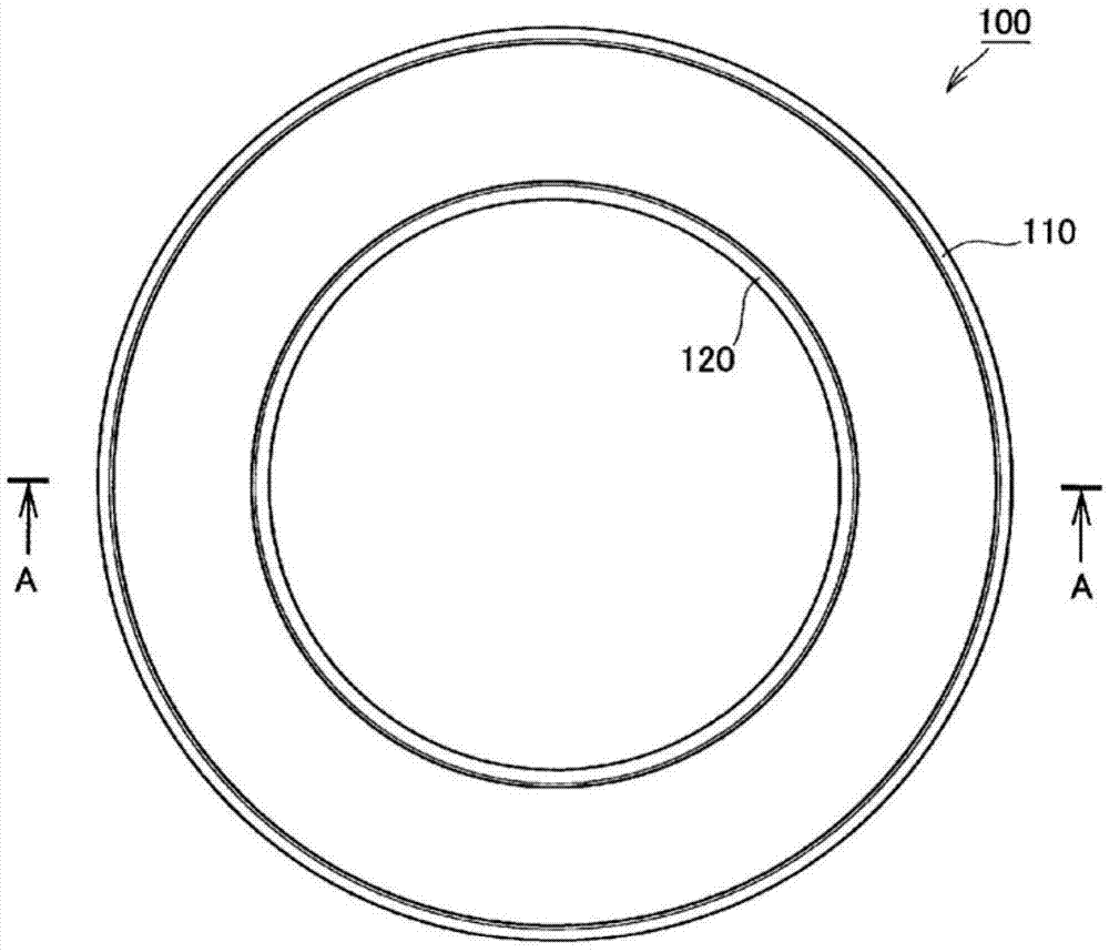
[0038] refer to Figure 1 ~ Figure 3 The sealing device of Example 1 of the present invention will be described. figure 1 is a side view of the sealing device of Embodiment 1 of the present invention, figure 2 is a plan view of the sealing device of Embodiment 1 of the present invention, image 3 is a cross-sectional view of the sealing device of Embodiment 1 of the present invention ( figure 2 A-A sectional view in).

[0039] The sealing device 100 of this embodiment is an annular mem...

Embodiment 2

[0069] Figure 11 Example 2 of the present invention is shown. In the above-mentioned first embodiment, the protruding heights of the outer peripheral convex part and the inner peripheral convex part of the sealing device are set to be equal, but in this embodiment, the protruding height of the outer peripheral convex part of the sealing device is set to be higher than that of the inner peripheral convex part. Structures when the protruding height is high.

[0070] The other structures and functions are the same as those in Embodiment 1, and the same components are given the same reference numerals, and their descriptions are appropriately omitted here. In addition, the method of manufacturing the sealing device is also the same as in the case of the above-mentioned first embodiment, and therefore its description is omitted.

[0071] Figure 11It is a schematic sectional view showing the state in which the sealing device according to the second embodiment of the present inv...

Embodiment 3

[0077] Figure 12 Example 3 of the present invention is shown. In the first embodiment described above, the protruding heights of the outer peripheral convex portion and the inner peripheral convex portion of the sealing device are equal, but in this embodiment, the protruding height of the inner peripheral convex portion of the sealing device is set to be higher than that of the outer peripheral convex portion. The structure of the case that stands out for height.

[0078] Since other structures and functions are the same as those in Embodiment 1, the same reference numerals are assigned to the same structural parts, and their descriptions are appropriately omitted. In addition, the manufacturing method of the sealing device is the same as that of the above-mentioned Example 1 except that the molded body is held by the middle mold instead of the outer mold at the time of demolding, so the description thereof is appropriately omitted.

[0079] Figure 12 It is a schematic s...


PUM


Abstract

Provided are: a method for manufacturing a sealing device, the method being configured so that, even if the sealing device has an annular inner peripheral protrusion on the inner peripheral side thereof, the method can increase manufacturing efficiency and enables cutting-off operation with high positional accuracy; and a sealing device which has increased sliding performance and which is less likely to break. A method for manufacturing a sealing device is provided with: a step for forming a cylindrical formed body (100a) consisting of a rubber-like elastic body, the formed body (100a) having circular cylinder surfaces (130) and annular outer peripheral protrusions (110), the circular cylinder surfaces (130) and the annular outer peripheral protrusions (110) being formed and arranged alternately on the outer peripheral side of the formed body (100a), the formed body (100a) also having circular cylinder surfaces and annular inner peripheral protrusions, the circular cylindrical surfaces and the annular inner peripheral protrusions being formed and arranged alternately on the inner peripheral side of the formed body (100a), the circular cylinder surfaces on the outer peripheral side and the circular cylinder surfaces on the inner peripheral side being arranged so as to be located at the same positions in the axial direction, the outer peripheral protrusions and the inner peripheral protrusions being arranged so as to be located at the same positions in the axial direction; and a cutting step for cutting off the formed body (100a) at each of the circular cylinder surfaces (130) on the outer peripheral side.

Description

technical field [0001] The invention relates to a manufacturing method and a sealing device for sealing an annular gap between two parts formed by relative reciprocating free movement. Background technique [0002] Conventionally, there is known a sealing device made of a rubber-like elastic body which seals an annular gap between two members which are relatively reciprocatingly movable. The sealing device is installed in an annular mounting groove provided on one of the two parts, and used in a sliding manner relative to the other part. As such a sealing device, a so-called D-ring having a D-shaped cross-section or a corner ring having a rectangular cross-section is known in which an annular protrusion is formed on the sliding side (see Patent Document 1). [0003] Among the above-mentioned seals, especially in the case of seals with a large inner diameter, it is more advantageous to cut and manufacture one molded body than separately form each pair of seals from the viewp...

Claims


Application Information

Patent Timeline
Patent Type & Authority Applications(China)
IPC IPC(8): F16J15/18
CPCF16J15/108F16J15/56F16J15/3204F16J15/328B29C2793/0027B29C2793/009B29C45/0053B29L2031/265F16J15/164B29K2101/00
Inventor 佐藤博明守尾亮庄岛大八
Owner NOK CORP
Learn More