
Plug and play method for travelling wave fault location system

A plug-and-play, traveling wave ranging technology, applied in the direction of the fault location, etc., can solve the problems of heavy workload of master station implementation and maintenance, heavy configuration workload of ranging master station, inconsistent parameters of multiple master stations, etc. , to achieve simple and convenient configuration, reduce the probability of errors, and ensure consistency

Active Publication Date: 2015-07-01
SHANDONG UNIV OF TECH +1
View PDF8 Cites 4 Cited by
  • Summary
  • Abstract
  • Description
  • Claims
  • Application Information

AI Technical Summary

Problems solved by technology

[0005] In this design method, the configuration workload of the distance measuring master station is heavy, and it is necessary to check the monitoring grid parameters with the distance measuring terminal. When the terminal monitors the line changes, the master station needs to be reconfigured. heavy workload
Moreover, the above-mentioned design method does not support multi-master stations well. When there are multiple master stations, each master station must repeatedly configure parameters, which can easily cause the problem of inconsistent parameters of multi-master stations.

Method used


Image

  • Plug and play method for travelling wave fault location system
  • Plug and play method for travelling wave fault location system
  • Plug and play method for travelling wave fault location system

Examples


Embodiment Construction

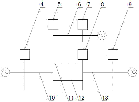
[0027] Figure 1~3 It is the best embodiment of the present invention, below in conjunction with attached Figure 1~3 The present invention will be further described.

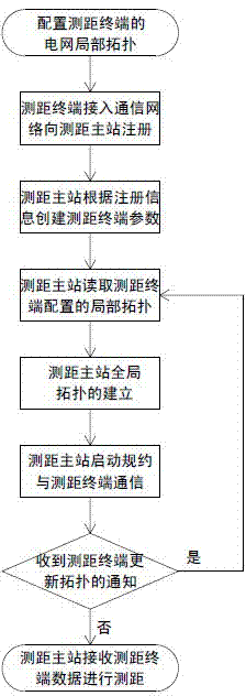
[0028] like image 3 As shown, the plug-and-play method of the traveling wave ranging system includes the following steps:

[0029] Step 1, configure the local topology of the power grid of the ranging terminal 3;

[0030] like figure 1 As shown, in the traveling wave ranging system, it includes a plurality of ranging master stations 1 and a plurality of ranging terminals 3, and the ranging terminals 3 and the ranging master stations 1 are connected and communicate through the communication network 2, and the ranging terminals 3 installed in substations. Each distance-measuring terminal 3 can configure the local topology of the power grid through the distance-measuring terminal configuration tool.

[0031] The local topology of the power grid refers to the line parameters monitored by a single ranging ter...


PUM


Abstract

A plug and play method for a travelling wave fault location system belongs to the field of electric power automation. Through the method, a distance measuring main station system does not need to manually create whole situation topological parameters of a monitored grid and parameters of distance measuring terminals, but each distance measuring terminal builds and stores the information of a line monitored by the distance measuring terminal and opposite terminal transformer substation. When the distance measuring terminals are electrically connected to a communication network where the main station is, a distance measuring main station can automatically identify the condition that the distance measuring terminals are on line, and the registrations of the distance measuring terminals on the distance measuring main station are realized. Meanwhile, the main station automatically reads the configuration information of each distance measuring terminal, and automatically builds a grid whole situation topology needed by the main station according to grid local topological information stored in each distance measuring terminal; the distance measuring terminals and the lines are monitored by the distance measuring main station, thus achieving the plug and play effect of the distance measuring terminals in the distance measuring main station system. When parameters of the lines monitored by the distance measuring terminals change, the whole situation topology of the main station is rebuilt by rereading the configuration parameters of the distance measuring terminals in time through the distance measuring main station.

Description

technical field [0001] The invention relates to a plug-and-play method of a traveling wave ranging system, which belongs to the field of electric power automation. Background technique [0002] When a power line fails, it is of great significance to quickly and accurately determine the fault location to ensure the safe, stable and economical operation of the power system. Traveling wave fault location technology has been widely used in power systems due to its high precision, wide application range and convenient use. [0003] The traveling wave ranging system actually used in the power system consists of multiple ranging terminals (TDU) and one or more ranging master stations. The ranging terminal completes the functions of traveling wave signal conversion, fault detection and discrimination, fault data sampling, and transmits fault data to the ranging master station; the ranging master station completes the reception of fault data transmitted by the ranging terminal, and ...

Claims


Application Information

Patent Timeline
IPC IPC(8): G01R31/08
Inventor 徐丙垠赵义奎李京赵月奉
Owner SHANDONG UNIV OF TECH
Learn More