
Multi-line system

A multi-connection system and indoor unit technology, applied in the field of multi-connection systems, can solve the problems of limited adjustment range, insufficient intelligence, more liquid and less gas, etc., and achieve the best effect.

Active Publication Date: 2017-05-03
GD MIDEA HEATING & VENTILATING EQUIP CO LTD +1
View PDF6 Cites 0 Cited by
  • Summary
  • Abstract
  • Description
  • Claims
  • Application Information

AI Technical Summary

Problems solved by technology

Among them, when the two-pipe heat recovery multi-connected system is operating in the main cooling mode, the outdoor unit sends a certain dryness of gas-liquid two-phase refrigerant to the indoor side. In theory, as long as the outdoor heat exchanger can achieve sufficiently fine control, the gas The dryness of the liquid two-phase refrigerant can be controlled at a fixed value, so that the cooling and heating internal units can achieve better results. However, in practice, there are often situations where there is more liquid and less gas or more gas and less liquid
[0003] In the related art, in order to achieve better results for the cooling and heating indoor units, it is necessary to distribute the liquid refrigerant to the cooling indoor unit and the gaseous refrigerant to the heating indoor unit in an appropriate proportion, usually by adjusting the first The pressure difference before and after the first electronic expansion valve is used to realize the distribution of refrigerant in the cooling and heating indoor units. However, the pressure difference before and after the first electronic expansion valve in the flow distribution device is controlled according to a certain value or within a certain range. This control strategy is often based on According to the data obtained by various simulation experiments, the adjustment range is not only limited, but also not intelligent enough, so it is difficult to make the system run in a better state.

Method used


Image

  • Multi-line system
  • Multi-line system
  • Multi-line system

Examples


Embodiment Construction

[0022] Embodiments of the present invention are described in detail below, examples of which are shown in the drawings, wherein the same or similar reference numerals designate the same or similar elements or elements having the same or similar functions throughout. The embodiments described below by referring to the figures are exemplary only for explaining the present invention and should not be construed as limiting the present invention.

[0023] The multi-connection system proposed according to the embodiment of the present invention is described below with reference to the accompanying drawings.

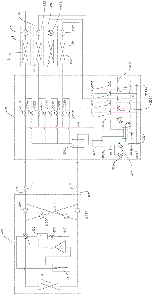
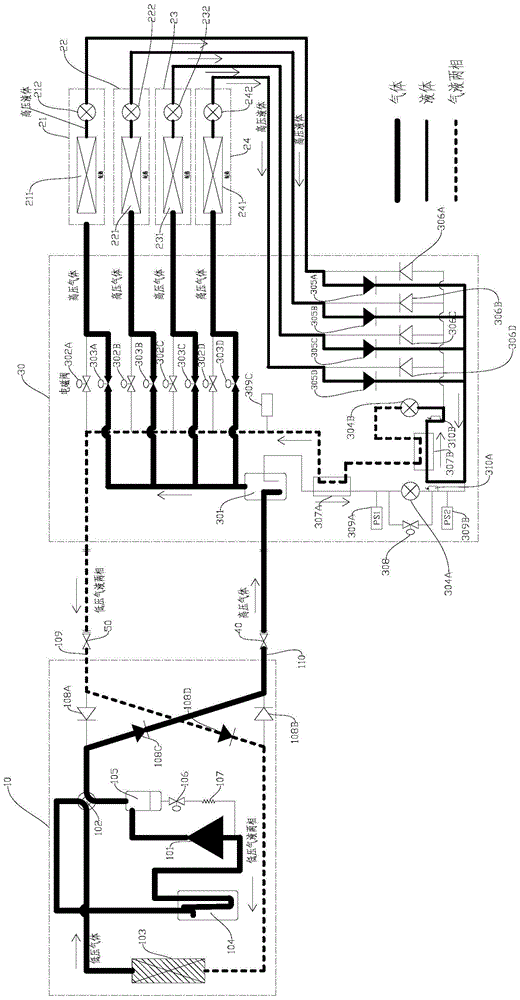
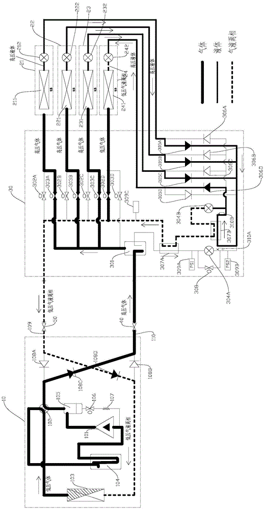
[0024] Such as Figure 1 to Figure 5 As shown, the multi-connected system of the embodiment of the present invention includes: an outdoor unit 10 , a plurality of indoor units such as four indoor units 21 , 22 , 23 , 24 , and a distribution device 30 .

[0025] Among them, the outdoor unit device 10 includes a compressor 101, a four-way valve 102, an outdoor heat exchanger 103...


PUM


Abstract

The invention discloses a multi-connection system, which includes an outdoor unit device, a flow distribution device, and multiple indoor unit devices. The flow distribution device includes a gas-liquid separator and a first electronic expansion valve. Control the first electronic expansion valve, and obtain the subcooling value of the heating indoor unit, the outlet air temperature of the heating indoor unit, the subcooling value of the refrigerant passing through the first electronic expansion valve, and each indoor If the opening value of the throttling element in any indoor unit device reaches the maximum opening degree, the flow splitting device will The current medium pressure control target value is adjusted by the outlet air temperature of the device and the subcooling degree value of the refrigerant passing through the first electronic expansion valve. The multi-connected system can automatically adjust the medium pressure control target value according to the state parameters of the running heating internal units, so as to achieve the best cooling and heating effect of the multi-connected system at the same time.

Description

technical field [0001] The invention relates to the technical field of air conditioning, in particular to a multi-connected system. Background technique [0002] With the continuous development of air conditioning technology and the strengthening of people's awareness of environmental protection, the heat recovery multi-line system is more and more popular in the market, and the two-pipe heat recovery multi-line system is one of the mainstream heat recovery multi-line systems in the market . Among them, when the two-pipe heat recovery multi-connected system is operating in the main cooling mode, the outdoor unit sends a certain dryness of gas-liquid two-phase refrigerant to the indoor side. In theory, as long as the outdoor heat exchanger can achieve sufficiently fine control, the gas The dryness of the liquid two-phase refrigerant can be controlled at a fixed value, so that the cooling and heating internal units can achieve better results. However, in practice, there are o...

Claims


Application Information

Patent Timeline
Patent Type & Authority Patents(China)
IPC IPC(8): F24F3/06F24F11/02F25B41/04F25B49/02F25B41/20
CPCF24F3/065F24F11/30F24F11/62F25B49/02F25B2600/00F24F11/64F25B41/20
Inventor 罗彬谭志军
Owner GD MIDEA HEATING & VENTILATING EQUIP CO LTD
Learn More