Internal roller of marking machine

A marking machine and roller technology, which is applied in the field of marking machines, can solve problems such as falling out and marking machines not working, and achieve the effects of convenient assembly and disassembly, prevention of axial movement, and prevention of bearing wear and tear

Inactive Publication Date: 2015-07-01
SHANGHAI ANDELAI AUTO PARTS
View PDF0 Cites 0 Cited by
  • Summary
  • Abstract
  • Description
  • Claims
  • Application Information

AI Technical Summary

Problems solved by technology

The structure of the existing marking machine roller is as follows: figure 1 As shown, the roller body 5 and the pin shaft 3 are provided with a needle roller 6, and the internal needle roller 6 will fall out of the roller due to wear during the up and down movement process, causing the marking machine to fail to work

Method used


Image

  • Internal roller of marking machine
  • Internal roller of marking machine

Examples


Embodiment Construction

[0014] The present invention will be described in detail below in conjunction with the accompanying drawings and specific embodiments. This embodiment is carried out on the premise of the technical solution of the present invention, and detailed implementation and specific operation process are given, but the protection scope of the present invention is not limited to the following embodiments.

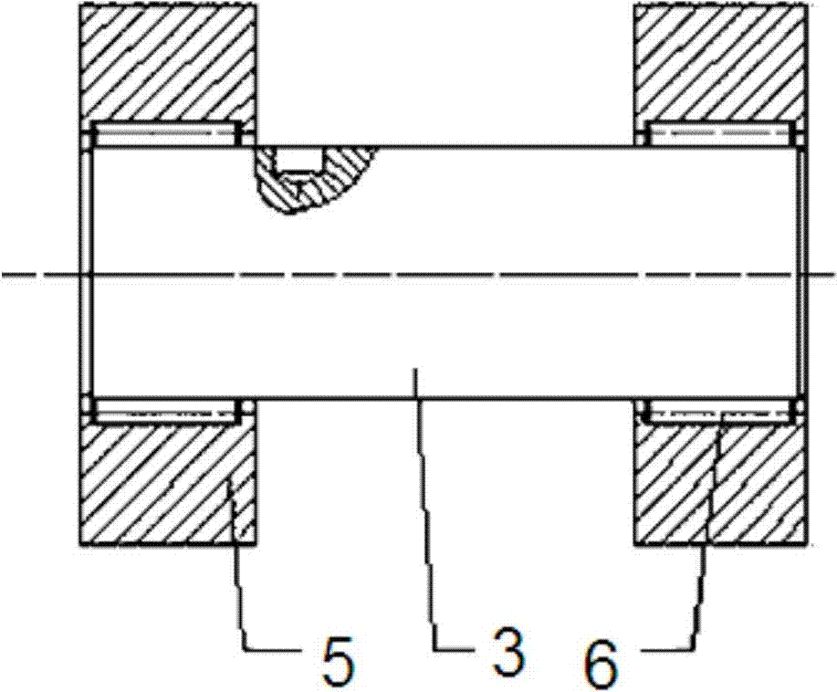
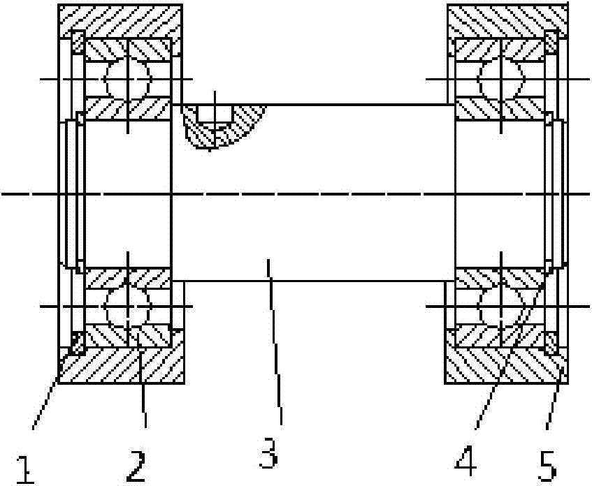
[0015] Such as figure 2 As shown, a roller inside a marking machine is sleeved on the pin shaft 3. The roller includes a roller body 5 and a ball bearing 2. The roller body 5 is arranged on the pin shaft 3 through the ball bearing 2. There are multiple ball bearings 2 described above, which are evenly distributed between the roller body 5 and the pin shaft 3 . A hole retaining ring 1 is provided between the roller body 5 and the ball bearing 2 , and a shaft retaining ring 4 is provided between the ball bearing 2 and the pin shaft 3 . The roller is axially fixed by the retaining rin...


PUM


Abstract

The invention relates to an internal roller of a marking machine, which coats a pin shaft. The roller comprises a roller body and a ball bearing, wherein the roller body is arranged on the pin shaft through the ball bearing. Compared with the prior art, the internal roller of the marking machine has such advantages as long service life and convenience for disassembly and maintenance.

Description

technical field [0001] The invention relates to a marking machine, in particular to an inner roller of the marking machine. Background technique [0002] The marking machine can print characters on PVC sleeves, heat shrinkable tubes, special self-adhesive labels, and marking tapes. It is generally used for secondary line marking of automobile related equipment. It is a special equipment for marking and can meet the needs of power plants, electrical appliances, etc. Equipment factories, substations, and electric power industry wire distinguishing signs need to be identified. The structure of the existing marking machine roller is as follows: figure 1 As shown, the roller body 5 and the pin shaft 3 are provided with a needle roller 6, and the inner needle roller 6 will fall out of the roller due to wear and tear during the up and down movement process, causing the marking machine to fail to work. Contents of the invention [0003] The purpose of the present invention is to...

Claims


Application Information

Patent Timeline
IPC IPC(8): F16C13/00
Inventor 应晓辉
Owner SHANGHAI ANDELAI AUTO PARTS
Why Eureka
Try Eureka