Electromagnetic energy-saving concrete vibrator

An energy-saving concrete technology, which is applied in construction, building structure, and building material processing, can solve the problems of high energy consumption, difficulty in realizing circular vibration, and affecting vibration amplitude and output power, etc., and achieves low energy consumption and low cost. Low, weak noise effect

Inactive Publication Date: 2016-09-07
浙江鼎川建设有限公司
View PDF6 Cites 2 Cited by
  • Summary
  • Abstract
  • Description
  • Claims
  • Application Information

AI Technical Summary

Problems solved by technology

[0003] The traditional concrete vibrator includes an external motor, a flexible shaft and a vibrating rod; the vibrating rod has an eccentric rotating mechanism inside, and the eccentric rotating mechanism is driven by an external motor through a flexible shaft. The disadvantage is that the cost of the flexible shaft is high and the transmission efficiency Low power consumption, high energy consumption; and the external motor is noisy, which seriously affects the surrounding environment, and is not conducive to the physical and mental health of construction workers
[0004] In view of the above reasons, the application number 201210013266.0, the patent name is an invention patent of a concrete multi-frequency vibrator, which proposes to set at least one set of mutually orthogonal electromagnet systems inside the vibrating rod, and the moving magnets in the system can move along the reciprocating motion in a linear direction, thereby producing mechanical fluctuations in two mutually orthogonal directions; however, this vibration is different from the vibration mode of a traditional vibrator, which continuously rotates around the axis of the vibrating rod , but the above-mentioned vibrator is difficult to achieve this kind of circular vibration, and its actual operation effect has yet to be practiced; in addition, because the moving magnet inside it needs to vibrate during the reciprocating motion, the radial slideway inside the vibrating rod is very short , causing the moving magnet to always be sucked back without sufficient acceleration, which seriously affects its vibration amplitude and output power. It can be seen that the vibration effect is limited

Method used


Image

  • Electromagnetic energy-saving concrete vibrator
  • Electromagnetic energy-saving concrete vibrator
  • Electromagnetic energy-saving concrete vibrator

Examples


Embodiment Construction

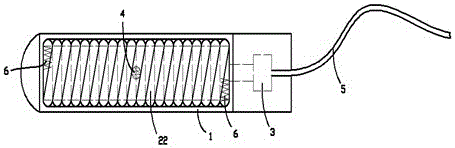
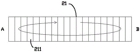
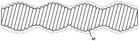
[0015] exist figure 1 , figure 2 In the shown embodiment, the electromagnetic energy-saving concrete vibrator includes a vibrating rod; the vibrating rod includes a shell 1 and an internal structure, and the internal structure includes a section of electromagnetic rod 21 extending along the axis of the vibrating rod; the electromagnetic rod 21 is composed of two or more sections of the same cylindrical electromagnet 211 connected in series, each section of electromagnet 211 is isolated and fixed by a non-magnetic material, thereby greatly weakening the influence of the magnetic force between adjacent electromagnets 211; The electromagnets 211 are respectively coupled to the same control module 3 located in the housing; as figure 2 As shown, assuming that one end of the electromagnetic rod is the A end, and the other end is the B end, the control module 3 connects each of the electromagnets 211 from the A end to the B end of the electromagnetic rod, and then from the B end t...


PUM


Abstract

The invention provides an electromagnetic energy-saving concrete vibrator which comprises a vibration bar. The vibration bar comprises a shell and an internal structure, the internal structure comprises an electromagnetic bar extending along the axis of the vibration bar, the electromagnetic bar is formed by connecting two or more segments of electromagnets in series, the segments of electromagnets are isolated through non-magnetism substance and are fixed, and the electromagnets are coupled with the same control module; one end of the electromagnetic bar is an end A, the other end of the electromagnetic bar is an end B, and the electromagnets are powered on circularly and alternately in a reciprocating mode through the control module from the end A to the end B of the electromagnetic bar first, then from the end B to the end A and finally from the end A to the end B; the control module is electrically connected with an external cable, the electromagnetic bar is surrounded by a spiral tube composed of non-iron magnetic substance, the two ends of the spiral tube are closed, a steel ball is arranged in the spiral tube, and the spiral tube and the electromagnetic bar are fixed to the shell. The vibrator is low in cost, small in energy consumption, low in noise and good in vibrating effect.

Description

technical field [0001] The invention relates to the field of building construction equipment, in particular to a concrete vibrator. Background technique [0002] In the field of building construction, in order to make the texture of the cast-in-place concrete uniform and remove the air bubbles in the concrete, it is necessary to vibrate the concrete after the pouring is completed; the basic equipment used in this process is a concrete vibrator. [0003] The traditional concrete vibrator includes an external motor, a flexible shaft and a vibrating rod; the vibrating rod has an eccentric rotating mechanism inside, and the eccentric rotating mechanism is driven by an external motor through a flexible shaft. The disadvantage is that the cost of the flexible shaft is high and the transmission efficiency Low energy consumption, high energy consumption; and the external motor is noisy, which seriously affects the surrounding environment, and is not conducive to the physical and men...

Claims


Application Information

Patent Timeline
Patent Type & Authority Patents(China)
IPC IPC(8): E04G21/08
Inventor 宋志梁
Owner 浙江鼎川建设有限公司
Why Eureka
Try Eureka