Method for achieving sensor point position objectification

A sensor and object-oriented technology, which is applied in the field of object-oriented sensor points to achieve the effect of improving development efficiency

Inactive Publication Date: 2015-06-24
TONGFANG SHENZHEN CLOUD COMPUTING TECH
View PDF3 Cites 5 Cited by
  • Summary
  • Abstract
  • Description
  • Claims
  • Application Information

AI Technical Summary

Problems solved by technology

[0012] The present invention aims to provide a method for realizing the objectification of sensor points, which reorganizes the points of independent equipment, realizes objectification of equipment through a custom model, and then binds the points of equipment through objects, and converts physical points Encapsulation to solve the problems existing in existing technology when faced with stand-alone devices

Method used


Image

  • Method for achieving sensor point position objectification
  • Method for achieving sensor point position objectification
  • Method for achieving sensor point position objectification

Examples


Embodiment Construction

[0033] In order to make the object, technical solution and advantages of the present invention clearer, the present invention will be further described in detail below in conjunction with the accompanying drawings.

[0034] The method for realizing the objectification of sensor points in the present invention comprises the following steps:

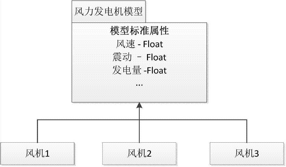
[0035] Step 1: abstract the device into a model, the model standardizes device attributes, and the model includes model constants and model attributes.

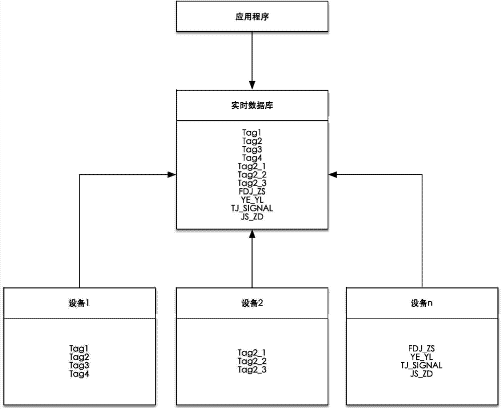
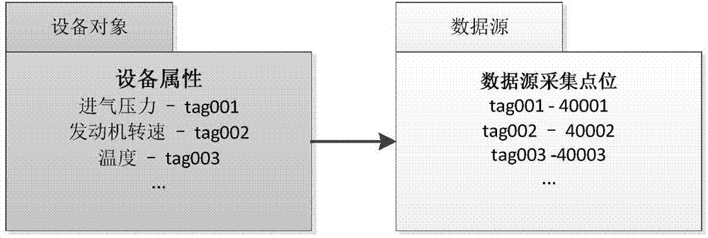
[0036] Step 2: Establish a device object based on the model. The device object maps the points in the data source into device object attributes. The data source is the collection terminal of the device, and the points in the data source include sensor points; the device object also Include private attributes.

[0037] Step 3: Construct the newly added equipment through the model, and the newly added equipment automatically inherits the model constants and model properties of the model. ...


PUM


Abstract

The invention discloses a method for achieving sensor point position objectification. The method comprises the steps: 1, a device is abstracted into a model, the model enables a device attribute to be standardized and includes a model constant and a model attribute; 2, a device object is established based on the model, the device object maps point positions in a data source into a device object attribute, the data source is an acquisition terminal of the device, and the point positions in the data source include a sensor point position. By means of the method, sensor point position objectification can be achieved, the point position of the independent device is reorganized, device objectification is achieved through a user-defined model, and then the point position of the device is bound through the object to package a physical point position so as to solve the problem existing when a sensor faces the independent device in the prior art.

Description

technical field [0001] The invention relates to a field solution for equipment, in particular to a method for realizing sensor point objectification. Background technique [0002] For equipment flow data, the flow data comes from the control system and sensors of the equipment, and generates analog and switch values ​​based on time series. In this field, the existing technical framework is an industrial real-time database, and a customized data collector. It is used to collect field data and support industrial application software. The existing mainstream technology is the industrial real-time historical database. The standard collector provided by the supporting database realizes the data collection of control systems such as PLC and DCS, and realizes the support of various industrial application software based on the real-time database. Under this technology, the real-time database collects all the original points, and the upper application accesses the original points. ...

Claims


Application Information

Patent Timeline
Patent Type & Authority Applications(China)
IPC IPC(8): G05B19/418
CPCG05B19/4183Y02P90/02
Inventor 李祥
Owner TONGFANG SHENZHEN CLOUD COMPUTING TECH
Why Eureka
Try Eureka