
Rotational inertia torsional pendulum period measuring method

A moment of inertia and period measurement technology, applied in the field of measurement, can solve the problems of high cost, high cost, low measurement accuracy, etc., and achieve the effect of simple structure, high cost performance, and overcoming low accuracy

Inactive Publication Date: 2015-06-24
YANCHENG INST OF TECH
View PDF4 Cites 3 Cited by
  • Summary
  • Abstract
  • Description
  • Claims
  • Application Information

AI Technical Summary

Problems solved by technology

[0009] However, the single-point repeat positioning accuracy of the Hall sensor is low. In terms of the torsion amplitude, its relative error has exceeded the order of 5‰, and the measurement accuracy is low.
In order to avoid the interference of ambient light and improve the triggering accuracy, the slit-type photoelectric tube requires the slit to be as small as possible, but too small slit will cause diffraction phenomenon and the output signal of the receiving tube is weak, and the measurement accuracy is also low
The binocular vision measurement method uses ultra-high-speed cameras and graphics workstations as hardware platforms, resulting in complex systems, high costs, and huge amounts of data processing
The grating measurement method needs to use a precision grating pair, and the cost is high; this method is an incremental measurement, and the loss or intrusion of pulses caused by interference will cause cumulative errors

Method used


Image

  • Rotational inertia torsional pendulum period measuring method
  • Rotational inertia torsional pendulum period measuring method
  • Rotational inertia torsional pendulum period measuring method

Examples


Embodiment Construction

[0029] Embodiments of the invention are described in detail below, but the invention can be practiced in many different ways as defined and covered by the claims.

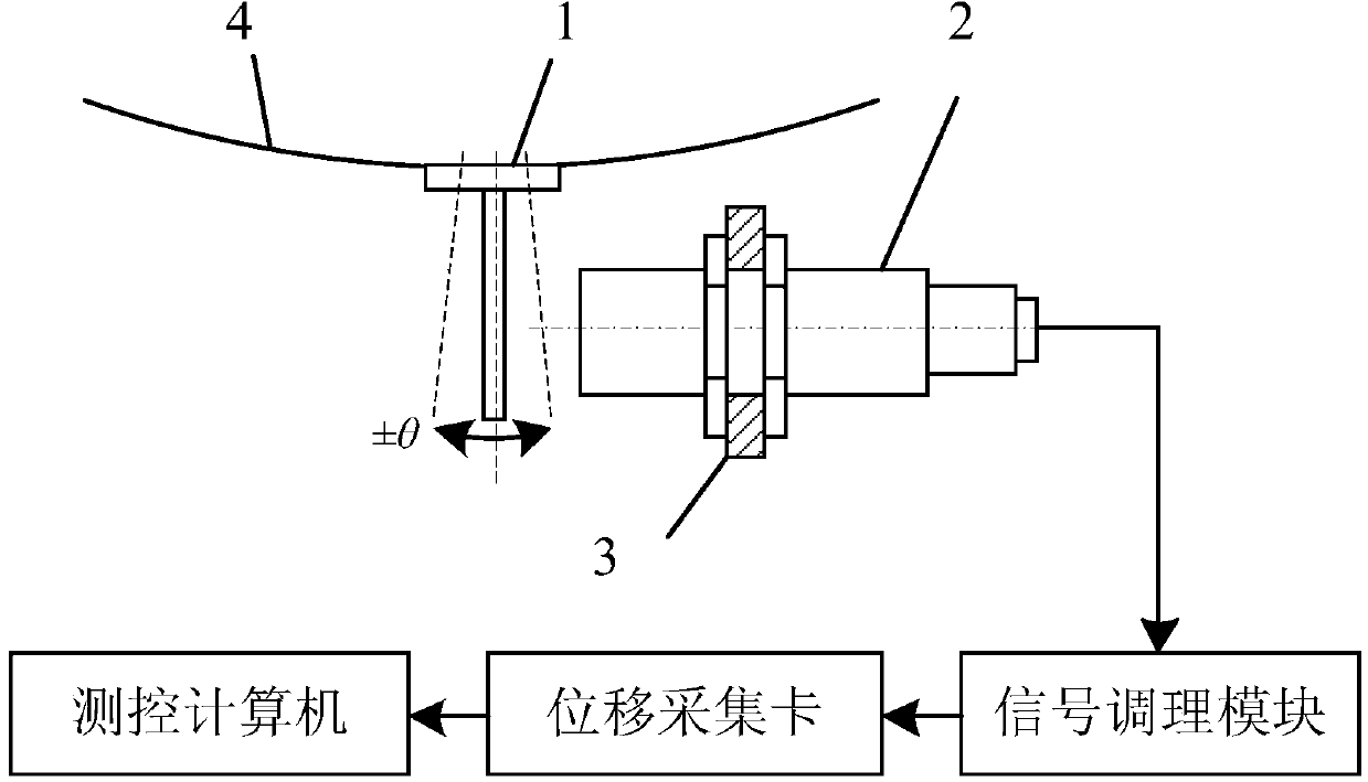
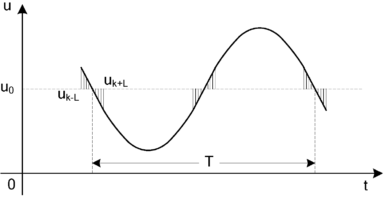
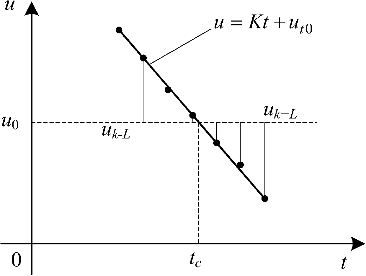
[0030] Please refer to Figure 1-3 , the present invention provides a method for measuring the moment of inertia torsion period, comprising: including: setting a radial baffle 1 on the turntable of the moment of inertia measurement system; disposing a displacement sensor 2 along the body direction of the turntable, and disposing the displacement sensor 2 on On the movement path of the radial baffle 1; after the air bearing of the turntable is stabilized, measure and record the static zero value of the turntable under static conditions; the vibration moment of inertia measurement system makes it torsion, and the radial vibration is collected by the displacement sensor 2 The baffle displacement signal of baffle 1; perform median filtering on the baffle displacement signal; calculate the absolute difference between th...


PUM


Abstract

A rotational inertia torsional pendulum period measuring method comprises the steps that a radial baffle is arranged on a rotary table of a rotational inertia measuring system; a displacement sensor is arranged in the tangential direction of the rotary table; the static zero value of the rotary table under the static condition is recorded; baffle displacement signals of the radial baffle are collected through the displacement sensor; an absolute difference value of median filter output and the static zero value is calculated, and a residual error sequence is obtained; a minimum extreme value of the residual error sequence is searched for within a preset length section, and prejudged zero crossing points of the baffle displacement signals are obtained; a displacement-time linear regression function related to the prejudged zero crossing points is obtained; a static zero line function is established according to the static zero value; the intersection point of the displacement-time linear regression function and the static zero line function is solved according to the displacement-time linear regression function and the static zero line function, and the intersection point is a corresponding accurate zero crossing point; the projection lengths of three adjacent accurate zero crossing points on a time axis are a torsional pendulum period of the rotary table. The rotational inertia torsional pendulum period measuring method has the advantages that the cost performance is high, the structure is simple and the method is easy to achieve.

Description

technical field [0001] The invention relates to the field of measurement, in particular to a method for measuring the period of rotational inertia and torsional pendulum. Background technique [0002] Moment of inertia is the measure of inertia when a rigid body rotates. Its value depends on the shape of the object, mass distribution and the position of the rotating shaft. It is an important characteristic parameter of aircraft attitude control. Its physical meaning is the size of the inertia of the object's rotation, which can generally be expressed as [0003] Usually, the distribution of the internal mass of the product or the shape of the product cannot meet the needs of theoretical calculations, so it is necessary to determine the moment of inertia of the product through measurement. The air bearing torsional pendulum moment of inertia measurement system has a large bearing capacity, the smallest damping effect, the highest measurement accuracy, and is widely used. ...

Claims


Application Information

Patent Timeline
IPC IPC(8): G01M1/10
Inventor 张春富何坚强辅小荣闫奇瑾
Owner YANCHENG INST OF TECH
Learn More