
A Maintainable Centrifugal Axial Fan

A maintainability and centrifugal shaft technology, which is applied to components, mechanical equipment, machines/engines, etc. of pumping devices for elastic fluids, can solve problems such as fan failures, difficulties, and high costs, and save maintenance Cost and maintenance efficiency, overcoming misjudgment defects, improving scientific and accuracy effects

Active Publication Date: 2017-01-11
CENT SOUTH UNIV +1
View PDF4 Cites 0 Cited by
  • Summary
  • Abstract
  • Description
  • Claims
  • Application Information

AI Technical Summary

Problems solved by technology

On the one hand, it is not advisable to blindly improve the process level and design level to reduce the failure rate of the product. On the other hand, this structure still cannot solve the problem of fan failure. The judgment depends on personal subjective experience and Disadvantages of misjudgment brought about by individual subjective feelings

Method used


Image

  • A Maintainable Centrifugal Axial Fan
  • A Maintainable Centrifugal Axial Fan

Examples


Embodiment 1

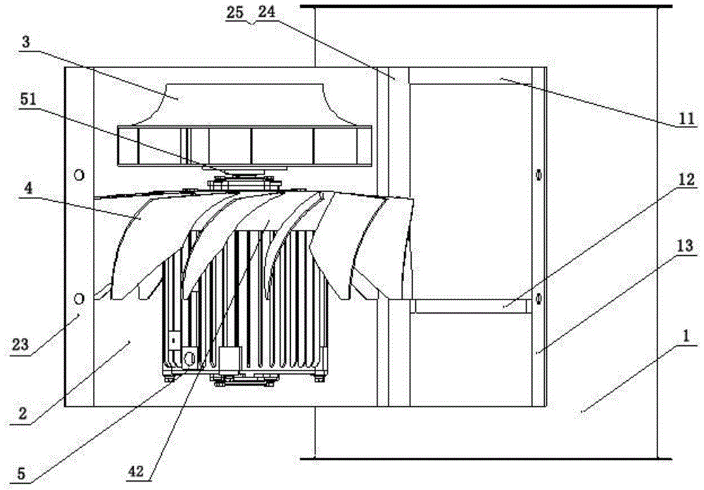
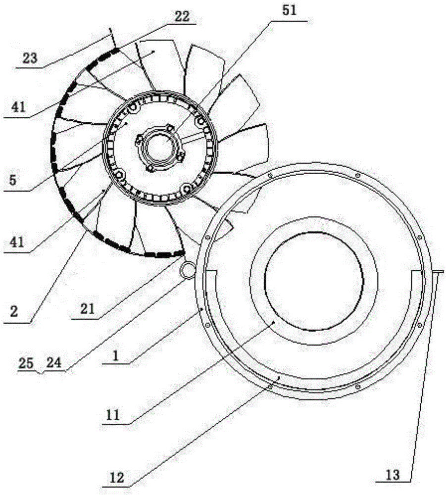
[0031] A maintainable centrifugal axial flow fan, see figure 1 and figure 2 , specifically including an air cylinder with a cavity at both ends, an arc door, a turning mechanism, a centrifugal impeller, a rear guide vane and a motor. The blower can be arranged horizontally or vertically, and in this embodiment, the vertical arrangement is used for description.

[0032] The upper end of the air cylinder 1 is provided with an air inlet channel 11 corresponding to the centrifugal impeller 3 , preferably: the cavity diameter of the air inlet channel 11 is the same as that of the centrifugal impeller 3 .

[0033] In the vertical direction, the side wall of the air cylinder 1 is provided with an opening, the opening is preferably located in the middle of the air cylinder 1, and the arc door 2 is arranged at the opening of the side wall of the air cylinder 1 and is connected with The size of the curved door 2 is matched, and one side of the curved door 2 can be turned over on the ...


PUM


Abstract

The invention provides a maintainable centrifugal axial-flow fan which comprises an air duct, an arc-shaped door, a turnover mechanism, a centrifugal impeller, rear guide blades and a motor, wherein the air duct is in the shape of a cylinder and provided with a cavity, and an opening is formed in the side wall of the air duct; the arc-shaped door is arranged on the opening portion of the side wall of the air duct, and the size of the arc-shaped door is matched with that of the air duct; the turnover mechanism can make one vertical line of one side of the arc-shaped door conduct turnover through taking one side edge which is close to and parallel to the vertical direction of the arc-shaped door, and the centrifugal impeller, the rear guide blades and the motor are arranged on the inner wall of the arc-shaped door in a concentric mode form top to bottom; when the arc-shaped door is closed, a cylindrical structure with the complete side wall can be formed by the air duct, and the whole structure is compact; when the arc-shaped door is closed, the centrifugal impeller, the rear guide blades and the motor are all located at the outer side of the opening of the side wall of the air duct, the overhauling is convenient, the maintenance cost is greatly reduced, and the maintenance efficiency is improved.

Description

technical field [0001] The invention relates to the field of fans, in particular to a centrifugal axial flow fan. Background technique [0002] Centrifugal axial flow fans can be widely used in national defense, rail transit, chemical industry and other fields, such as cooling various centrifugal compressors, ship power systems and traction motors, etc., and play an important role in the normal operation of various equipment. [0003] At present, the centrifugal axial flow fan is limited to the requirements of the geometric space, and the impeller and the motor are placed in the air cylinder, and the structure is relatively compact; in order to increase the pressure and flow of the fan, the air inlet channel and the rear guide vane are often added in the fan to meet the cooling requirements. Equipment requirements for air volume and air pressure. This structure requires that the rear guide vane is welded with the air duct, the impeller is centered, the front guide vane is p...

Claims


Application Information

Patent Timeline
Patent Type & Authority Patents(China)
IPC IPC(8): F04D25/08F04D29/40F04D29/26F04D29/00
CPCF04D25/08F04D29/002F04D29/263F04D29/403F04D29/441
Inventor 侯志泉杨明智刘智远周雷军翟方志
Owner CENT SOUTH UNIV
Learn More