


Quick Research
Generate reliable direction feasibility study reports for your R&D in just a few steps.

Technical Q&A
Discover and master advanced knowledge NOW. Basics, ideas, possibilities, all at once.

Find Solutions
As an expert in R&D theories, this can generate solutions to your technical problems instantly.

Evaluate Feasibility
Analyze your overall solution with one click, know your potential R&D risks in advance.

Monitor Landscape
Get weekly tech updates, stay abreast of the latest tech innovations and key insights.
Monitoring method based on time triggering Ethernet
A time-triggered, Ethernet technology, applied in the field of communication, can solve the problems such as the inability to meet the monitoring requirements of high-reliability switching networks, the inability to realize the monitoring of data flow information and time information, and achieve the effect of meeting the monitoring requirements.
- Summary
- Abstract
- Description
- Claims
- Application Information
AI Technical Summary
Problems solved by technology
Method used
Image

Examples
Embodiment Construction
[0020] In time-triggered Ethernet, the guardianship function should reside on the switch so that the guardianship can shut down the inputs and outputs of the switch. The guardian has its own time synchronization algorithm and is able to receive all messages coming into the switch.
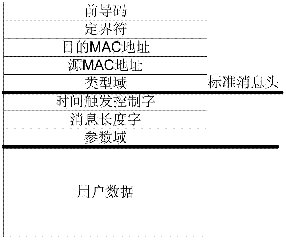
[0021] A typical frame format includes a preamble, a fixed field, a destination MAC address, a source MAC address, a type field, and the like. The time-triggered message further includes a time-triggered control word, a message length, a parameter field, and the like. Messages are divided into time-triggered messages, protocol control messages, and rate-limited messages through type field information. The time trigger message format is as follows figure 1 shown.
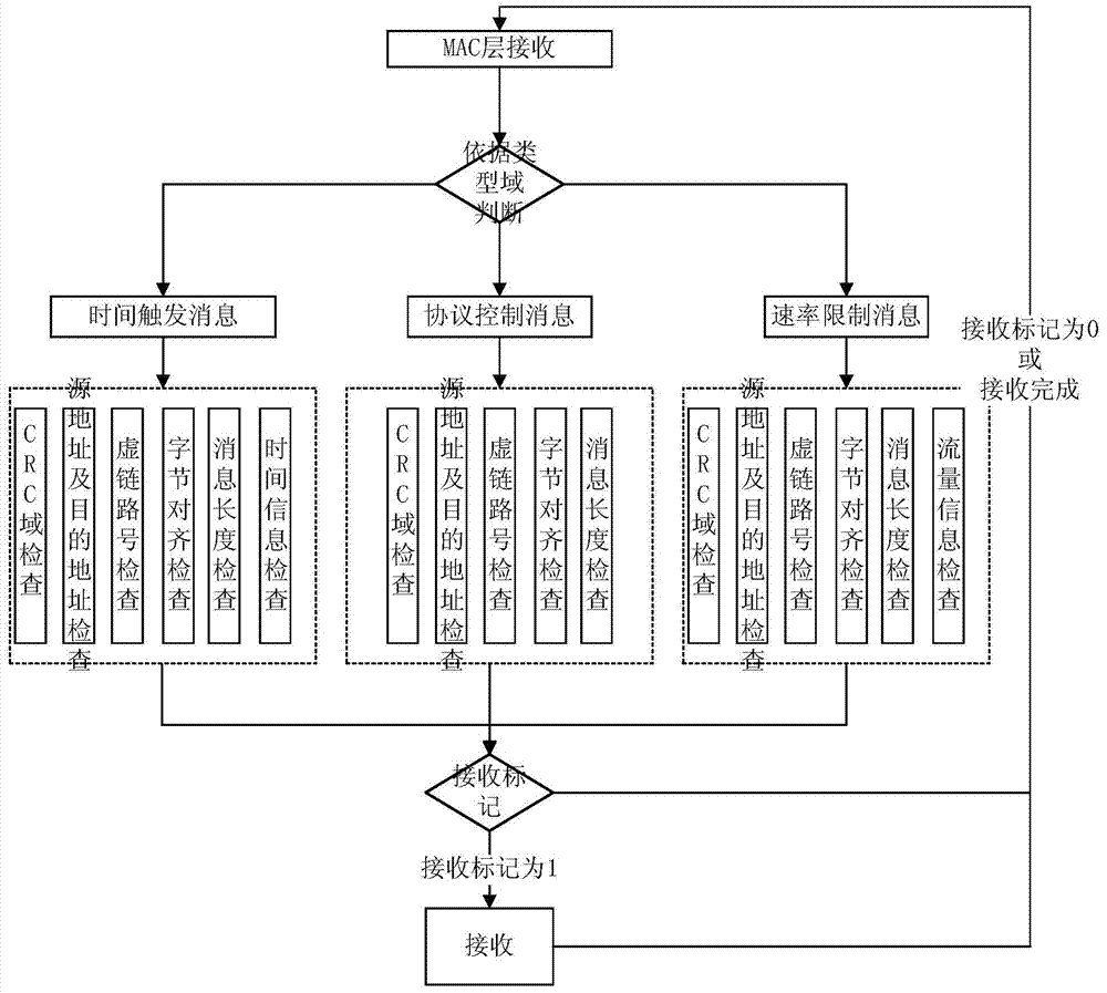
[0022] A monitoring method based on time-triggered Ethernet, see figure 2 ,described as:
[0023] 1] Perform register configuration first, including configuration of source address register, destination address register, virtual lin...
PUM
 Abstract
Description
Claims
Application Information
 - R&D Engineer
- R&D Manager
- IP Professional
- Industry Leading Data Capabilities
- Powerful AI technology
- Patent DNA Extraction
Browse by: Latest US Patents, China's latest patents, Technical Efficacy Thesaurus, Application Domain, Technology Topic, Popular Technical Reports.
© 2024 PatSnap. All rights reserved.Legal|Privacy policy|Modern Slavery Act Transparency Statement|Sitemap|About US| Contact US: help@patsnap.com