Photovoltaic module mounting rack

A technology for photovoltaic modules and mounting racks, applied in the field of photovoltaic module mounting racks, can solve the problems of easy displacement of fastening blocks, block wiring, reduce the internal space of C-shaped steel, etc., and achieve the effect of saving internal space and not easy to shift.

Inactive Publication Date: 2015-06-17
JIANGXI JINKO PV MATERIAL
View PDF4 Cites 2 Cited by
  • Summary
  • Abstract
  • Description
  • Claims
  • Application Information

AI Technical Summary

Problems solved by technology

However, after adopting such a method, the fastening block is easy to shift, and it is easy to reduce the internal space of the C-shaped steel due to the large space occupied by the spring, and it is easy to block the wiring

Method used


Image

  • Photovoltaic module mounting rack
  • Photovoltaic module mounting rack
  • Photovoltaic module mounting rack

Examples


Embodiment Construction

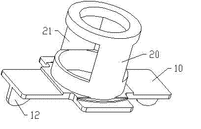
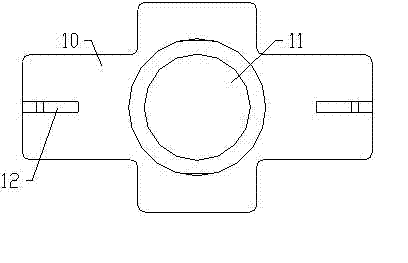
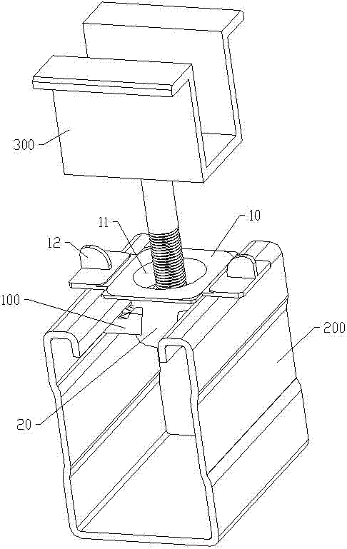
[0012] Examples, see Figure 1 to Figure 3 Shown: a photovoltaic module installation frame, used to fasten the fastening block 100 on the side wall inside the C-shaped steel 200 and realize the suspension of the fastening block 100 . Wherein, the fastening block 100 is provided with screw holes (not shown in the figure) for screwing and cooperating with the screws on the middle pressure block 300 . Furthermore, the photovoltaic module installation frame includes a support plate 10 placed on the upper part of the opening of the C-shaped steel 200 to ensure that the photovoltaic module installation frame does not fall into the C-shaped steel 200 . The middle part of the support plate 10 is provided with a first through hole 11 for the screws on the middle pressing block 300 to pass through. An installation cylinder 20 is integrally formed on the upper surface of the support plate 10 . The mounting cylinder 20 is transparent up and down and its inner cavity is aligned with the ...


PUM


Abstract

The invention discloses a photovoltaic module mounting rack which is used for abutting a fastening block against the inner side wall of C-shaped steel. The fastening block is provided with a screw hole which is in threaded connection fit with a screw on a middle press block. The photovoltaic module mounting rack comprises a support plate, the middle of the support plate is provided with a first through hole, and an installation cylinder is integrally molded on the upper surface of the support plate. The installation cylinder is hollow in the vertical direction, an inner cavity of the installation cylinder is aligned with the first through hole, and at the same time, two second through holes through which the fastening block penetrates are formed in the side wall of the installation cylinder. The photovoltaic module mounting rack is made of a plastic material. Preferably, shifting lugs are integrally molded on the lower surface of the support plate. The photovoltaic module mounting rack has the advantages that the fastening block is not easy to displace, the internal space of the C-shaped steel is saved, and distribution is not easy to block.

Description

technical field [0001] The invention relates to the technical field of photovoltaic accessories, in particular to a photovoltaic component installation frame. Background technique [0002] In the photovoltaic industry, it is often necessary to fixedly connect the middle pressure block and the fastening block, and then press the fastening block into the C-shaped steel, so as to realize the connection between the middle pressure block and the C-shaped steel, and further the middle pressure block After being fixed in a suitable position, install the solar panel on the C-shaped steel to realize the installation of the solar panel. At present, during the installation process, springs are often used to fasten the fastening block on the inner side wall of the C-shaped steel to prevent the fastening block from falling into the bottom of the C-shaped steel. However, after adopting such a method, the fastening block is easy to displace, and it is very easy to reduce the internal spac...

Claims


Application Information

Patent Timeline
Patent Type & Authority Applications(China)
IPC IPC(8): H02S20/30
CPCH02S20/00Y02E10/50
Inventor 祝菊芬黄琳田倩
Owner JIANGXI JINKO PV MATERIAL
Why Eureka
Try Eureka