Integrated inductor

An integrated inductance, part of the technology, applied in the field of inductors, can solve the problems of magnetic flux leakage and increased power loss of equipment, and achieve the effect of reducing costs and avoiding the phenomenon of magnetic flux leakage.

Active Publication Date: 2015-06-17
EATON INTELLIGENT POWER LTD
View PDF5 Cites 5 Cited by
  • Summary
  • Abstract
  • Description
  • Claims
  • Application Information

AI Technical Summary

Problems solved by technology

This gap will inevitably lead to the occurrence of magnetic flux leakage
The phenomenon of flux leakage may cause some eddy current loss to the metal surrounding the inductor, which eventually leads to increased power loss of the equipment containing the inductor

Method used


Image

  • Integrated inductor
  • Integrated inductor
  • Integrated inductor

Examples


Embodiment Construction

[0025] In order to make the object, technical solution and advantages of the present invention more clear, the present invention will be further described in detail below in conjunction with specific embodiments. It should be understood that the specific embodiments described here are only used to explain the present invention, not to limit the present invention.

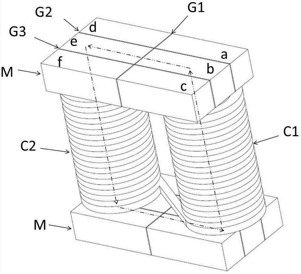
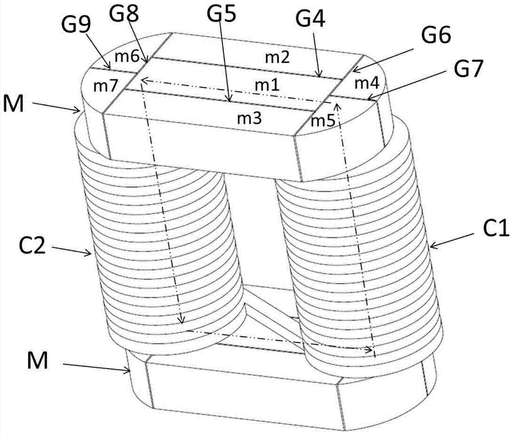
[0026] This embodiment provides an integrated inductor, the structure of which is as follows figure 2 shown, including:

[0027] The first winding C1 and the second winding C2 are connected to each other, wherein the first winding C1 and the second winding C2 are wound on different inner cores ( figure 2 not shown in);

[0028] Two external magnetic cores M located outside the first winding C1 and the second winding C2 are located on both sides of the first winding C1 and the second winding C2 for making the internal magnetic cores located inside the first winding C1 and the second winding C2 The cores are conn...


PUM


Abstract

An integrated inductor comprises a first winding (C1) and a second winding (C2); a first internal magnetic core in the first winding (C1) and a second internal magnetic core in the second winding (C2); and at least one external magnetic core (M) outside the first winding (C1) and the second winding (C2), used for being connected to end portions of the first and second internal magnetic cores to form a magnetic path, the external magnetic core (M) being formed by multiple sub-magnetic cores joint with each other; the magnetic conductivity of at least one sub-magnetic core of the multiple sub-magnetic cores is greater than the magnetic conductivity of other sub-magnetic cores, and the at least one sub-magnetic core at least covers a part of end surfaces of the first internal magnetic core and the second internal magnetic core. The integrated inductor can alleviate the phenomenon of flux leakage, and can reduce costs of the magnetic cores.

Description

technical field [0001] The invention relates to an inductor, in particular to an integrated inductor with a magnetic core composed of multiple blocks. Background technique [0002] At present, with the continuous introduction of high-efficiency and high-power UPS or inverter equipment, in order to meet market requirements and improve competitive advantages, the design and cost requirements for inductors are also getting higher and higher. As the size of the inductor increases, the size of the magnetic core increases accordingly. However, the manufacturing cost of a monolithic, large-volume magnetic core is very high. Therefore, in the prior art, splicing is usually used to form a large-volume magnetic core by splicing a plurality of relatively small blocks. This magnetic core Often referred to as an integrated inductor. [0003] figure 1 One such integrated inductor is shown in . Such as figure 1 As shown, the integrated inductor includes a first winding C1 and a second...

Claims


Application Information

Patent Timeline
Patent Type & Authority Applications(China)
IPC IPC(8): H01F17/04H01F27/24
CPCH01F3/10H01F37/00H01F2003/106H01F27/24H01F3/14H01F27/2823
Inventor 郑大为王文廖西征刘丹
Owner EATON INTELLIGENT POWER LTD
Why Eureka
Try Eureka