Power-on protection control circuit for photoelectric tracker

A photoelectric tracker and control circuit technology, applied in the direction of electrical program control, sequence/logic controller program control, etc., can solve the problem of long time consumption of the system, achieve the effect of improving reliability, simplifying wiring relationship, and reducing quantity

Active Publication Date: 2017-10-17
西安应用光学研究所
View PDF4 Cites 0 Cited by
  • Summary
  • Abstract
  • Description
  • Claims
  • Application Information

AI Technical Summary

Problems solved by technology

Moreover, the existing photoelectric tracker does not have a power-off protection device. In the case of misoperation, if the system power-off switch is disconnected, the entire system will be directly powered off, and all individual devices will stop working. It takes a long time to restart the system. An emergency can have fatal consequences

Method used


Image

  • Power-on protection control circuit for photoelectric tracker
  • Power-on protection control circuit for photoelectric tracker
  • Power-on protection control circuit for photoelectric tracker

Examples


Embodiment Construction

[0017] Describe the present invention below in conjunction with specific embodiment:

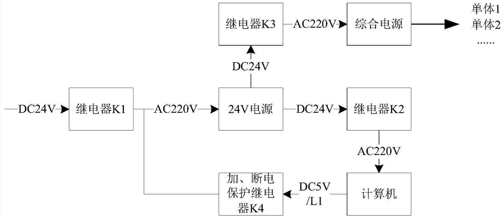
[0018] This embodiment discloses a power-on protection control circuit for a photoelectric tracker, including a control computer, an integrated power supply, a control circuit module and a power supply module.

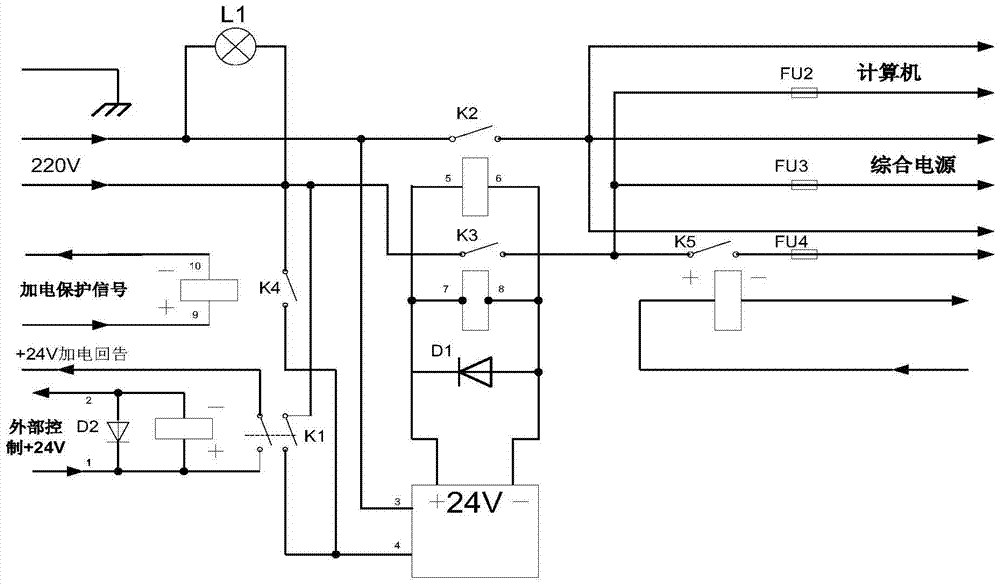
[0019] like figure 1 and figure 2 As shown, the control circuit module includes four relays K1, K2, K3, K4. The first relay K1 is controlled by an external control switch. K1 input terminal 1 receives the positive terminal of the external control +24V voltage, and K1 input terminal 2 is connected to the +24V ground. When the external control +24V is turned on, K1 pulls in.

[0020] After K1 is pulled in, 220V AC voltage is input to +24V power module N1 (ports 3 and 4), and N1 outputs +24V voltage. The power module controls the second relay K2 and the third relay K3. The +24V positive terminal of N1 is input to the 5th pin of K2, and the +24V ground of N1 is input to the 6th pin ...


PUM


Abstract

The invention provides a powering-up protection control circuit for a photoelectric tracking instrument. The powering-up protection control circuit comprises a control computer, a comprehensive power source, a control circuit module and a power module. The control circuit module comprises four relays. The first relay and the fourth relay are connected in parallel to achieve double-path power supply of external alternating current to the power module. The first relay is controlled by an external control switch. The fourth relay is controlled by the control computer. The second relay achieves the power supply to the control computer through the external alternating current, the third relay achieves the power supply to the comprehensive power source through the external alternating current, the second relay and the third relay are controlled by the power module, and when the external alternating current supplies power to the power module, the second relay and the third relay are closed. The comprehensive power source supplies power to all controlled units of the photoelectric tracking instrument. Compared with the prior art, the problem that when misoperation exists in the photoelectric tracking instrument and an external +24 V switch is turned off, the whole system powers down, and therefore the reliability of the photoelectric tracking instrument is improved.

Description

technical field [0001] The invention belongs to the field of photoelectric technology control, in particular to a power-on protection control circuit for a photoelectric tracker. Background technique [0002] The photoelectric tracker can realize the real-time measurement of the position parameters of the moving target. It generally includes multiple controlled units such as a TV detector, an infrared thermal imager, a laser range finder, a control computer, a servo system, a gyroscope and a fan. In the traditional photoelectric tracker, there is only one switch to control the power-on process of the system, and each monomer system is powered on and powered off at the same time. Since the loads of each monomer are capacitive and inductive loads, the surge generated by simultaneous power-on and power-off The large current poses a great challenge to the electromagnetic compatibility of the system and the tolerance of the power supply system. Therefore, it is very important to...

Claims


Application Information

Patent Timeline
Patent Type & Authority Patents(China)
IPC IPC(8): G05B19/04
CPCG05B19/04
Inventor 芦峰刘建平陆培国王虎张宝宜李广良刘汉平何玉兰
Owner 西安应用光学研究所
Why Eureka
Try Eureka