Method for dividing density degrees of gravelly soil foundations through surface-wave inversion shear wave velocities

A technology of shear wave and compactness, which is applied in the engineering field, can solve the problems of difficult drilling, low detection efficiency, and limited detection depth, and achieve the effect of overcoming the difficulty of drilling

Active Publication Date: 2015-06-17
WUHAN SURVEYING GEOTECHN RES INST OF MCC
View PDF7 Cites 11 Cited by
  • Summary
  • Abstract
  • Description
  • Claims
  • Application Information

AI Technical Summary

Problems solved by technology

The direct method is mainly the pit measurement method, that is, digging pits, weighing, and measuring volume. It is an original and commonly used method, and the measurement results are relatively accurate and reliable. Due to these limitations, the large-scale use of the pit measurement method in the quality inspection of large-sized gravel fillings is limited; the indirect methods mainly include dynamic penetrating sounding method, compaction settlement observation method, continuous compaction control method, Loading plate method, surface wave method
[0003] The dynamic penetrating sounding method, the compaction settlement observation method, the continuous compaction control method, and the bearing plate method all have problems such as difficult drilling, long time, high cost, and limited detection depth.

Method used


Image

  • Method for dividing density degrees of gravelly soil foundations through surface-wave inversion shear wave velocities
  • Method for dividing density degrees of gravelly soil foundations through surface-wave inversion shear wave velocities
  • Method for dividing density degrees of gravelly soil foundations through surface-wave inversion shear wave velocities

Examples


specific Embodiment approach

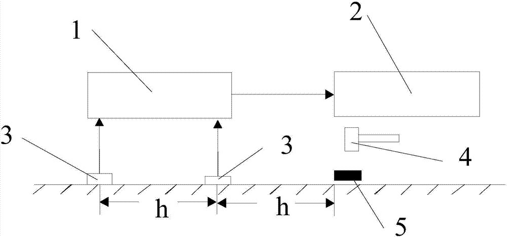
[0063] figure 2 It is a schematic diagram of the on-site detection layout of the ground transient Rayleigh wave measurement. In the figure, 1 is the seismograph, 2 is the analyzer, 3 is the geophone, 4 is the heavy hammer, and 5 is the backing plate. The Rayleigh shear wave velocity is collected according to the operating procedures, and this process should be completed through field operations. We adopt the single-ended excitation method, arrange 24 channels of detectors, the detector frequency is 4Hz, the channel spacing is 1m, the offset distance is 5m, the number of sampling points is 2048, and the sampling interval is 250us. Taking the measuring point as the center of symmetry, the detector is evenly placed on the ground in a straight line, so that it fits tightly with the ground and stands upright. Impact the ground vertically with a heavy hammer, and the seismograph records the ground vibration signals received by the geophone. Repeat the above steps 3 to 5 times to ...

Embodiment

[0066] The test was carried out in three different sites, so the test sites were all with less earthwork and more stonework, and the stonework was mainly backfilled. The construction overview of dynamic compaction is shown in Table A and Table B, and there are three kinds of fillers.

[0067] Table A List of dynamic compaction parameters for soil-rock mixed fill area

[0068]

[0069] Note: The particle size of gravel in gravel soil is less than 500mm.


PUM

PropertyMeasurementUnit
Particle sizeaaaaaaaaaa

Abstract

The invention discloses a method for dividing the density degrees of gravelly soil foundations through the surface-wave inversion shear wave velocities. Compared with the prior art, the method has the obvious advantages that as Rayleigh waves have the different propagation velocities in the gravelly soil dynamic-compaction foundations with the different density degrees, the propagation velocity of the Rayleigh waves in a surface slack layer serves as the standard, and the relationships between the Rayleigh waves and the density degrees in the gravelly soil dynamic-compaction foundations with the different density degrees are built. The density degrees of the gravelly soil dynamic-compaction foundations are simply, rapidly and automatically determined, and the problems that during current detection, the exploration difficulty is large, time is long, cost is high, and the detection depth is limited are solved.

Description

technical field [0001] The invention relates to the technical field of engineering, in particular to a method for dividing the foundation compactness of dynamic rammed large-diameter gravel soil by using surface wave inversion of shear wave velocity Vs and its wave velocity ratio ΔVs. Background technique [0002] At present, large-size gravel soil is used as dynamic compaction backfill. Because of its strong adaptability to different ground conditions, small settlement, good stability, good seismic performance, simple construction, and easy repair, it can be used in mountainous areas. Local materials are obtained, and there are relatively abundant sources of materials, which have significant advantages in terms of technical and economic indicators, especially in the construction of land in mountainous areas, a large number of on-site backfilling is used. However, due to the large particle size and uneven particle distribution of gravel soil, it brings great difficulties to ...

Claims


Application Information

Patent Timeline
IPC IPC(8): E02D1/00
CPCE02D1/00
Inventor 王小章高杰杨麟峰熊建华郑俊李志强周培峰赵谦黎明
Owner WUHAN SURVEYING GEOTECHN RES INST OF MCC
Why Eureka
Try Eureka