Eureka AIR delivers breakthrough ideas for toughest innovation challenges, trusted by R&D personnel around the world.

Field bus controller and method

A field bus and controller technology, applied in program control, comprehensive factory control, electrical program control, etc., can solve problems such as low down-loading efficiency, huge service, training and technical support costs, and difficulties in handling engineering and technical problems.

Inactive Publication Date: 2015-06-10
XIAN THERMAL POWER RES INST CO LTD
View PDF6 Cites 7 Cited by
  • Summary
  • Abstract
  • Description
  • Claims
  • Application Information

AI Technical Summary

Problems solved by technology

[0005] (1) The purchase cost of foreign fieldbus controllers is high, and the technology is closed. It is difficult for ordinary thermal engineers and technicians in power plants to deal with daily engineering and technical problems.
[0006] (2) The field bus controller is monopolized by foreign system suppliers, and the use of foreign field bus control systems will generate huge additional service, training and technical support costs, resulting in unnecessary expenses for the power plant in the later stage
[0007] (3) At present, each technology of the field bus controller has its own system, and there are few standard interfaces provided to the outside, or the external interfaces are not disclosed, which is very difficult for the expansion of the system
[0008] (4) The online modification and downloading of existing controllers is inefficient, time-consuming, and poor in security. Generally, the system does not support the online configuration downloading function
[0009] (5) The operation of controller control configuration and system database configuration is complicated, and the man-machine interface and operating habits are not friendly. Since the control systems are all foreign systems, English interfaces are mostly used, resulting in domestic power plant thermal and engineering personnel operating and Inconvenient to use
[0010] (6) The control algorithm and function blocks provided by the controller are not perfect, and cannot fully meet the requirements of domestic power plants for complex control and energy-saving optimization. In order to realize a certain function, complex configuration work is often required to realize it

Method used


Image

  • Field bus controller and method
  • Field bus controller and method

Examples


Embodiment Construction

[0045] The present invention will be further described in detail below in conjunction with the accompanying drawings and specific embodiments.

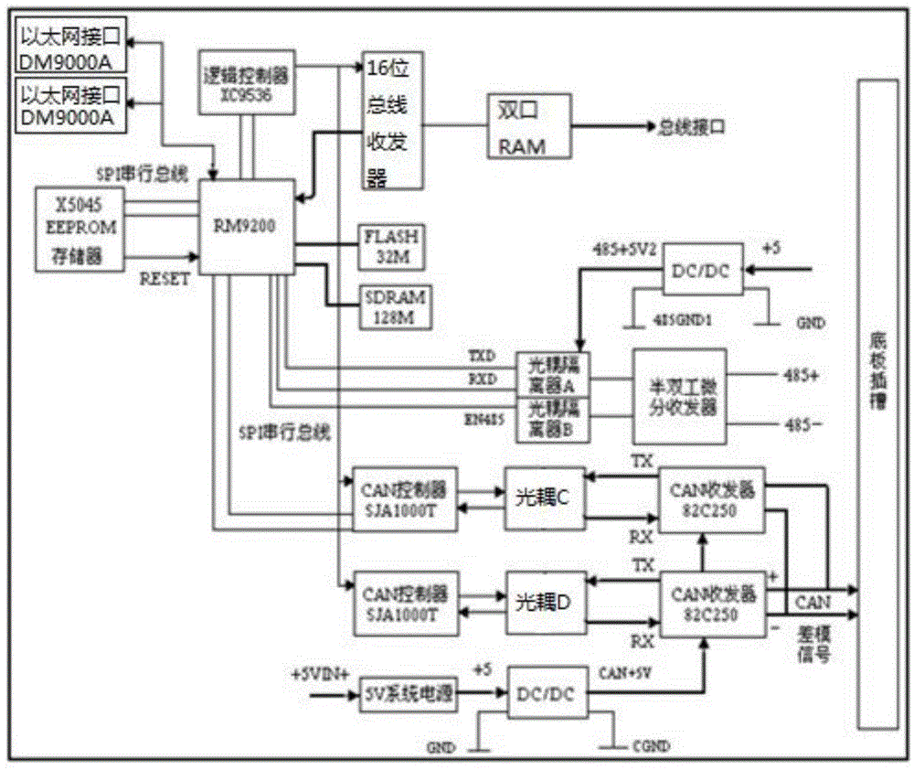
[0046] like figure 1As shown, a field bus controller of the present invention includes two redundant Ethernet interfaces DM9000A provided to the outside, RM9200 connected to the Ethernet interface DM9000A through a bidirectional data bus, and the data pins SD0 to SD15 of the Ethernet interface DM9000A Connect to the data pins D0 to D15 of RM9200 respectively, among which SD0 is connected to D0, SD1 is connected to D1, and so on, and SD15 is connected to D15; the CS# pin of the Ethernet interface DM9000A is connected to the NCS3 pin of RM9200, and the The RESET pin is connected to PA25 of RM9200, the INT pin of Ethernet interface DM9000A is connected to PA23 of RM9200, the CMD pin of Ethernet interface DM9000A is connected to A2 pin of RM9200; it also includes dual-port RAM, two-way CAN The bus controller SJA1000T, the logic controlle...


PUM


Abstract

The invention provides a field bus controller and method. The controller comprises two Ethernet interfaces DM9000A, a logic controller XC9536, a 16-bit bus transceiver ALVC16245, a double-interface RAM, an X5045EEPROM memory, an RM9200 processor, a 32M flash memory, a 128M SDRAM memory, a CAN bus DC / DC power isolator, an optical coupled isolator A, an optical coupled isolator B, a half-duplex differential transceiver, two CAN controllers SJA1000T, a CAN transceiver 82C250, a 5V system power supply, a 485 communication DC / DC power isolator, a board-level serial bus and a double-interface RAM bus interface, wherein the two Ethernet interfaces DM9000A are interconnected. The invention further provides a control method. The field bus controller is easily produced and operated, rich in control functional blocks, simple to achieve a system, and high in reliability.

Description

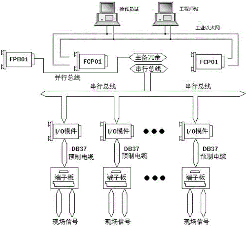
technical field [0001] The invention relates to the technical field of power plant field bus control, in particular to a field bus controller and a method. Background technique [0002] Fieldbus Control System (FCS for short) is a real-time control communication network that interconnects the lowest level of automation field controllers and field intelligent instrumentation equipment. It follows the ISO OSI open system interconnection reference model for all or part of the communication Protocol, which can realize two-way serial multi-node digital communication. FCS is a fully decentralized, fully digital, fully open and interoperable new-generation production process automatic control device. It is a real-time network control system that interconnects the lowest level of automation field controllers and field intelligent instrumentation equipment. FCS is composed of multi-segment fieldbus, various intelligent field instruments (including flow, pressure, temperature, actuat...

Claims


Application Information

Patent Timeline
IPC IPC(8): G05B19/418
CPCY02P90/02G05B19/41845G05B19/4186
Inventor 高海东李晓博刘茜王春利崔逸群
Owner XIAN THERMAL POWER RES INST CO LTD
Why Eureka
Eureka Blog
Learn More