
Method for forecasting DC biasing current influence of multiple DC grounding electrodes on sites in different operation modes

A technology of DC bias and operation mode, applied in the direction of measuring electricity, measuring devices, measuring electrical variables, etc., can solve the problems of calculation error, inability to realize DC bias prediction, and inaccurate simulation of the ground modeling part, and achieve early improvement. The effect of early warning capabilities

Active Publication Date: 2015-06-10
STATE GRID SICHUAN ELECTRIC POWER CORP ELECTRIC POWER RES INST +1
View PDF2 Cites 16 Cited by
  • Summary
  • Abstract
  • Description
  • Claims
  • Application Information

AI Technical Summary

Problems solved by technology

Establish the target power grid model through simulation calculation, and calculate the influence of DC bias magnetic field under different operating conditions of the power grid in areas with multiple DC grounding poles according to the geographical location of each substation and DC grounding pole, as well as the DC resistance of the transmission line and the DC resistance of the transformer However, due to the complex geological conditions of the power grid, the ground modeling part in the simulation model cannot accurately simulate the real situation, which brings errors to the calculation, and cannot accurately calculate the DC current distribution in the power grid, let alone realize multi-DC grounding Prediction of the influence of DC bias magnetism under different operating conditions of power grids in polar regions

Method used


Image

  • Method for forecasting DC biasing current influence of multiple DC grounding electrodes on sites in different operation modes
  • Method for forecasting DC biasing current influence of multiple DC grounding electrodes on sites in different operation modes
  • Method for forecasting DC biasing current influence of multiple DC grounding electrodes on sites in different operation modes

Examples


Embodiment Construction

[0057] The technical scheme of the present invention is described in detail below.

[0058] 1. How the prediction method works

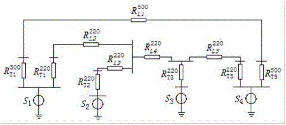
[0059] When the DC transmission single-pole ground circuit is running, the DC grounding electrode will inject (or draw out) the DC current during the line operation to the ground, and the surface potential of the DC grounding electrode and its vicinity will rise (or drop). At this time, the main transformer of the nearby substation The neutral point is at different ground potentials, causing DC current to flow in (or out) from the neutral point of the transformer, and the DC current passes through the transformer winding to cause DC bias.

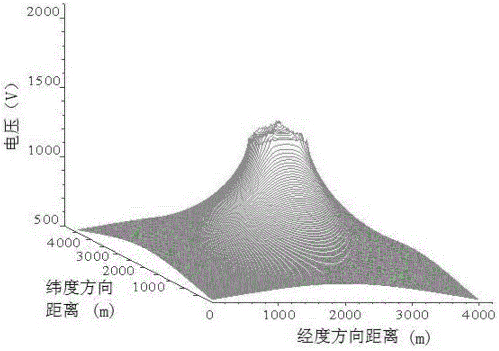
[0060] Establish a simulation model based on the geological structure and soil type of the DC grounding pole and the area where the substation is located, and calculate the potential distribution of the DC grounding pole in the vicinity of the DC grounding pole through the simulation software CDEGS; potential; th...


PUM


Abstract

The invention discloses a method for forecasting DC biasing current influence of multiple DC grounding electrodes on sites in different operation modes. According to the method, a DC online monitoring device is mounted at the neutral point of a transformer near the DC grounding electrodes to grab the actual measurement data of distribution of the DC biasing current; next, the resistivity and the thickness of each layer of soil are adjusted to correct a simulation model according to the actual measurement data, and then the corrected soil model is used for forecasting the influence conditions of the DC biasing of the power grid in the area having multiple DC grounding electrodes under different operating conditions; for the transformer having the DC current exceeding a set value, protection measures can be applied to the transformer in advance, and therefore, the purpose of targeted DC biasing current protection can be achieved. The method has the beneficial effects that the early warning capability on the DC biasing of the power grid transformers is improved and the effective protection measures can be adopted for the transformers having great DC biasing risk conveniently and immediately.

Description

technical field [0001] The invention relates to the technical field of substation operation management, in particular to a method for predicting the influence of DC bias current on a station under different operation modes of multiple DC grounding poles. Background technique [0002] In recent years, my country's direct current transmission has developed rapidly, and the problem of unbalanced distribution of energy and load centers has been effectively alleviated. However, the problem of direct current bias of transformers caused by direct current transmission has become more and more prominent. When transformers are biased by direct current, there will be aggravated vibration and noise. Phenomena such as increase and local overheating will cause problems such as loose tensioning parts inside the transformer, broken windings, damage to insulating materials, loose and bent iron sheets, etc. If the duration is too long, it will also cause damage to the transformer. The DC bias ...

Claims


Application Information

Patent Timeline
Patent Type & Authority Applications(China)
IPC IPC(8): G01R31/00
Inventor 蒋伟张星海甘德刚
Owner STATE GRID SICHUAN ELECTRIC POWER CORP ELECTRIC POWER RES INST
Learn More