Eureka AIR delivers breakthrough ideas for toughest innovation challenges, trusted by R&D personnel around the world.

Resistor verifying system

A technology of resistance and resistance value, applied in the direction of measuring resistance/reactance/impedance, measuring electrical variables, measuring devices, etc., can solve problems such as inaccurate control of sampling resistance, and achieve the effect of being suitable for promotion and reducing calibration errors.

Inactive Publication Date: 2015-06-10
DALIAN DONGPU MECHANICAL & ELECTRICAL
View PDF0 Cites 13 Cited by
  • Summary
  • Abstract
  • Description
  • Claims
  • Application Information

AI Technical Summary

Problems solved by technology

[0002] Resistors are indispensable electronic components in electronic circuits, and their accuracy directly affects the reliability and performance of electronic circuits. Resistors can be divided into ordinary resistors and precision resistors due to the difference in nominal accuracy. The accuracy of ordinary resistors is generally It is about 5%, and the accuracy of precision resistors must be at least 1%, or even higher, and the resistance value is affected by various factors such as temperature, resistance material and conductor length, so the actual resistance of the same nominal value There is often a certain difference in the resistance value, so it is very necessary to check the resistance value of the resistance in actual use, especially for the resistance in the sampling circuit, the error of the sampling resistance itself will directly lead to inaccurate control

Method used


Image

  • Resistor verifying system

Examples


Embodiment Construction

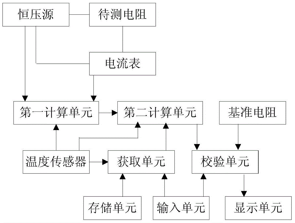
[0021] Such as figure 1 A resistance calibration system shown includes: a reference resistance whose resistance value is known at 20°C; a resistance to be measured; connected to both ends of the resistance to be measured and used to apply a constant voltage U across the resistance to be measured Constant voltage source; connected in series in the loop formed by the resistance to be measured and the constant voltage source, an ammeter for detecting the loop current I of the resistance to be measured; a temperature sensor for detecting the current ambient temperature t; connecting the constant voltage source, the ammeter and The temperature sensor is used to obtain the first calculation unit of the resistance value R of the resistance to be measured under the current ambient temperature t by using the formula R=U / I according to the constant voltage U applied to both ends of the resistance to be measured and the current I of the circuit; Connect the temperature sensor, be used to...


PUM


Abstract

The invention discloses a resistor verifying system. The resistor verifying system comprises a reference resistor, a to-be-verified resistor, a constant voltage source, an ampere meter, a temperature sensor, a first calculating unit, an acquiring unit, a second calculating unit and a verifying unit, wherein the constant voltage source is used for applying constant voltage U to ends of the to-be-verified resistor; the ampere meter is used for detecting the current I of a loop where the to-be-verified resistor is located; the temperature sensor is used for detecting current environment temperature t; the constant voltage source, the ampere meter and the temperature sensor are connected through the first calculating unit, and the first calculating unit is used for using the formula R=U / I to obtain the resistance of the to-be-verified resistor under the current environment temperature t; the acquiring unit is used for acquiring the resistivity temperature coefficient alpha corresponding to conductor materials according to the conductor materials of the to-be-verified resistor and the current environment temperature t; the second calculating unit is used for using formula R20=R / (1+ alpha (t-20)) to obtain the resistance R20 of the to-be-verified resistor at 20 DEG C; the verifying unit is used for performing difference value verification on the resistance R20 of the to-be-verified resistor according to the resistance of the reference resistor at 20 DEG C. By the system, verification errors can be reduced effectively, and accuracy and practicality are achieved.

Description

technical field [0001] The invention relates to a resistance calibration system. Background technique [0002] Resistors are indispensable electronic components in electronic circuits, and their accuracy directly affects the reliability and performance of electronic circuits. Resistors can be divided into ordinary resistors and precision resistors due to the difference in nominal accuracy. The accuracy of ordinary resistors is generally It is about 5%, and the accuracy of precision resistors must be at least 1%, or even higher, and the resistance value is affected by various factors such as temperature, resistance material and conductor length, so the actual resistance of the same nominal value There is often a certain difference in the resistance value, so it is very necessary to check the resistance value of the resistor in actual use, especially for the resistor used in the sampling circuit, the error of the sampling resistor itself will directly lead to inaccurate contro...

Claims


Application Information

Patent Timeline
IPC IPC(8): G01R27/02
Inventor 王榕英
Owner DALIAN DONGPU MECHANICAL & ELECTRICAL
Why Eureka
Eureka Blog
Learn More