
In-mold riveting automatic feeding mechanism

An automatic feeding and in-mold riveting technology, applied in the field of in-mold riveting automatic feeding mechanism, can solve the problems of high manufacturing cost and use cost, low production efficiency, easy failure, etc., and achieve low failure, high production efficiency and riveting accuracy high effect

Active Publication Date: 2019-08-20
KUNSHAN HAO YUN PRECISION MOLD
View PDF9 Cites 2 Cited by
  • Summary
  • Abstract
  • Description
  • Claims
  • Application Information

AI Technical Summary

Problems solved by technology

[0002] Many products are riveted together by metal stamping parts. In actual production, there are two manufacturing methods. One is to stamp the metal stamping parts separately first, and then use riveting equipment to rivet the two metal stamping parts together. This structure It requires multiple procedures to operate, low production efficiency, labor-intensive, and prone to adverse situations such as missing riveting. The other is to use in-mold riveting, and the rivets are sent into the mold one by one through automated equipment for riveting. However, automated equipment manufacturing High cost and use cost, prone to failure, requires operators to have corresponding operating capabilities, and has high requirements for operators

Method used


Image

  • In-mold riveting automatic feeding mechanism
  • In-mold riveting automatic feeding mechanism
  • In-mold riveting automatic feeding mechanism

Examples


Embodiment

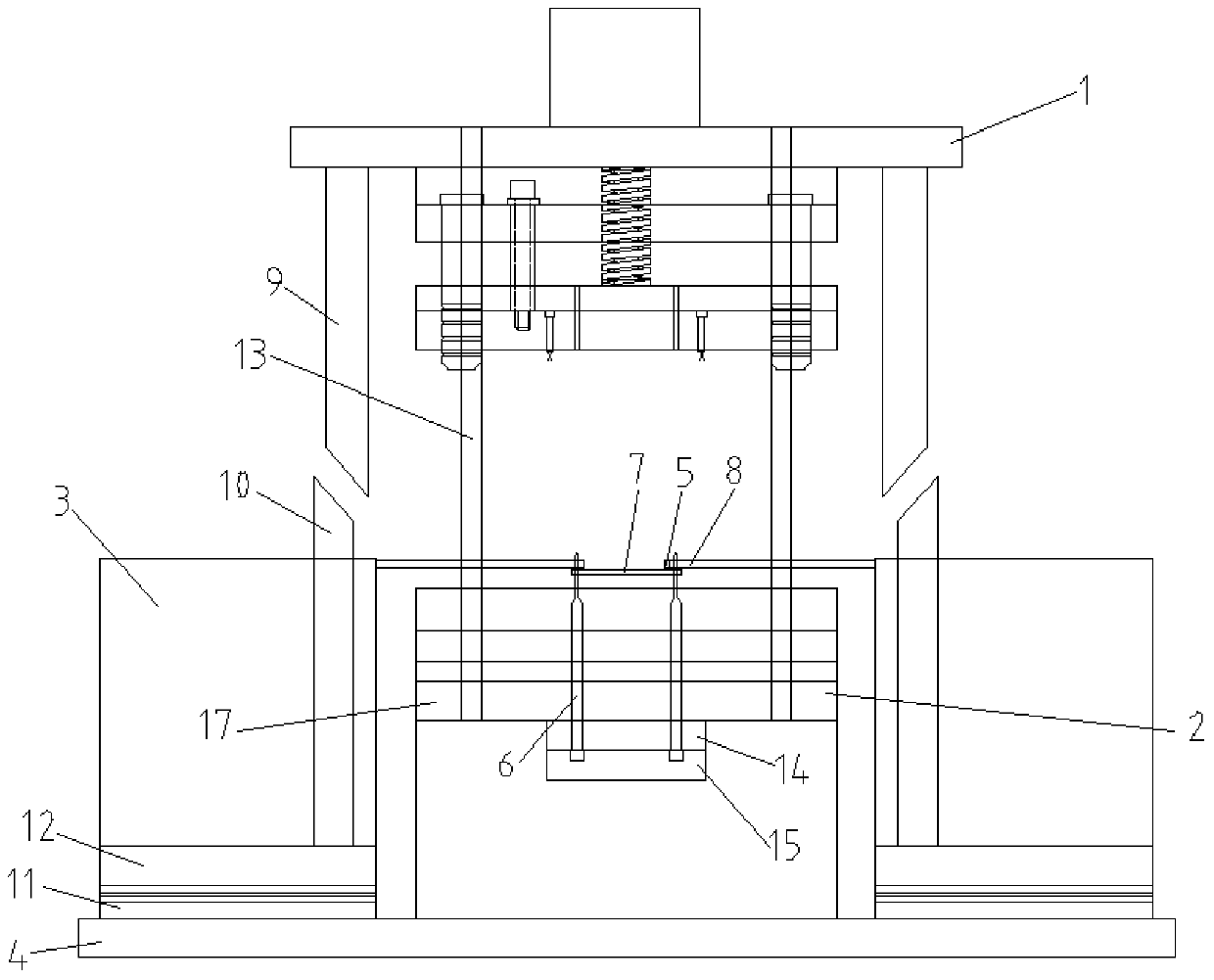
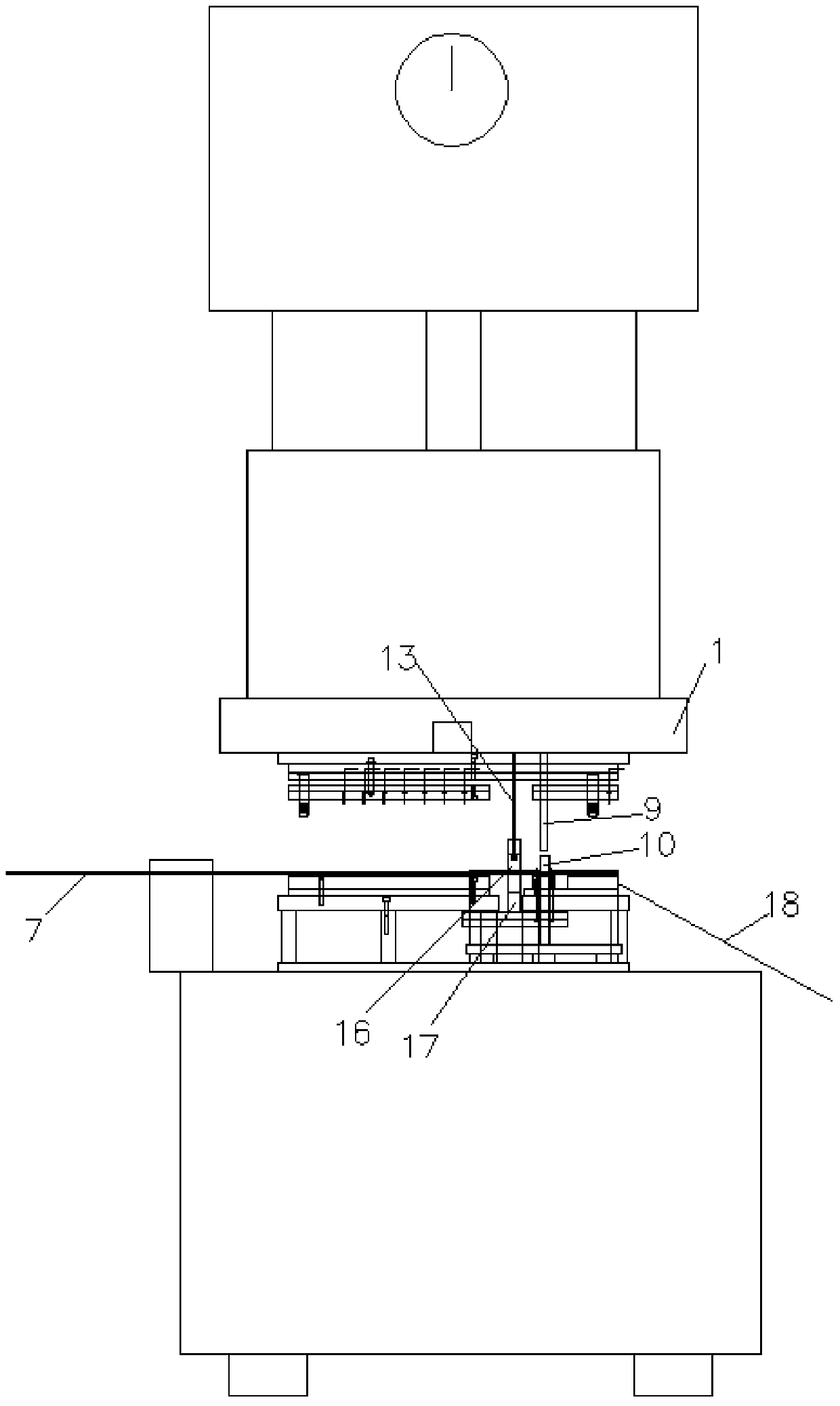
[0018] Embodiment: an automatic feeding mechanism for in-mold riveting, including stamping upper die 1, stamping lower die 2, vibrating plate 3, supporting plate 4, vibrating plate driving device, rivet baffle plate 5, positioning pin 6 and positioning pin driving device, The stamping upper die 1 can be reciprocated longitudinally and positioned directly above the stamping lower die 2, the positioning pin 6 can be vertically lifted and inserted in the stamping lower die 2, the positioning pin driving device drives the positioning pin 6 to move vertically, and the supporting plate 4. It is fixedly positioned on the outside of the stamping lower die 2. The vibrating plate 3 can slide back and forth toward the inner direction of the stamping upper die and the stamping lower die and is positioned on the supporting plate 4. The rivet at the end of the vibrating disc discharge channel 8 can be coaxially aligned with the positioning pin 6. Yes, the rivet baffle 5 is positioned and ins...


PUM


Abstract

The invention discloses an automatic feeding mechanism for riveting in a die. The automatic feeding mechanism comprises a stamping upper die, a stamping lower die, a vibrating disc, a support plate, a vibrating disc drive device, a rivet retaining plate, a positioning pin and a positioning pin drive device, wherein the stamping upper die is positioned right above the stamping lower die in a longitudinal reciprocating manner, the positioning pin is disposed in the stamping lower die in a longitudinal liftable manner, the positioning pin drive device drives the positioning pin to longitudinally move up and down, the support plate is fixedly positioned on the outer side of the stamping lower die, the vibrating disc which can slide towards the internal directions of the stamping upper die and the stamping lower die in a reciprocating manner is positioned on the support plate, the rivet at the tail end of the discharge passage of the vibrating disc can coaxially directly face the positioning pin, the rivet retaining plate is positioned at the tail end of the discharge passage of the vibrating disc and can provide set resistance to the rivet at the tail end of the discharge passage of the vibrating disc, and the vibrating disc drive device drives the vibrating disc to move. The automatic feeding mechanism which is mechanically driven is simple in structure, energy saving, free of technical requirements on operators, less prone to failure, and high in production efficiency.

Description

technical field [0001] The invention relates to an automatic feeding device, in particular to an automatic feeding mechanism for in-mold riveting. Background technique [0002] Many products are riveted together by metal stamping parts. In actual production, there are two manufacturing methods. One is to stamp the metal stamping parts separately first, and then use riveting equipment to rivet the two metal stamping parts together. This structure It requires multiple procedures to operate, low production efficiency, labor-intensive, and prone to adverse situations such as missing riveting. The other is to use in-mold riveting, and the rivets are sent into the mold one by one through automated equipment for riveting. However, automated equipment manufacturing The cost and use cost are high, and failures are prone to occur. Operators are required to have corresponding operating capabilities, and the requirements for operators are high. Contents of the invention [0003] In o...

Claims


Application Information

Patent Timeline
Patent Type & Authority Patents(China)
IPC IPC(8): B21J15/32B21J15/38
Inventor 张光豪
Owner KUNSHAN HAO YUN PRECISION MOLD
Learn More