
Embedded touch display panel and drive method thereof

A technology for a touch display panel and a driving method, which is applied to static indicators, optics, instruments, etc., can solve problems such as affecting display quality and reducing transmittance.

Inactive Publication Date: 2015-06-03
HANNSTAR DISPLAY CORPORATION
View PDF5 Cites 12 Cited by
  • Summary
  • Abstract
  • Description
  • Claims
  • Application Information

AI Technical Summary

Problems solved by technology

However, because the in-cell touch display panel directly manufactures the sensing and driving electrodes in each pixel, this will sacrifice part of the aperture ratio, resulting in low transmittance and affecting display quality.

Method used


Image

  • Embedded touch display panel and drive method thereof
  • Embedded touch display panel and drive method thereof
  • Embedded touch display panel and drive method thereof

Examples


Embodiment Construction

[0014] The following is a detailed description of preferred embodiments of the present invention with the accompanying drawings. The following description and drawings use the same reference numerals to indicate the same or similar elements, and repeated descriptions of the same or similar elements are omitted.

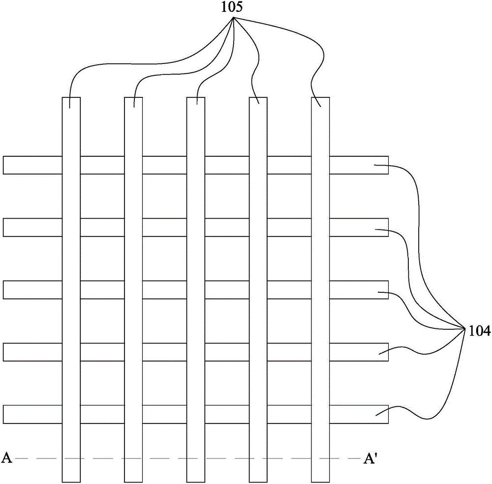
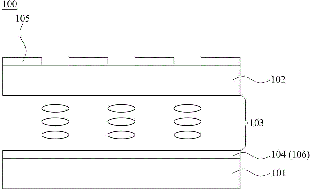
[0015] Please refer to figure 1 as well as figure 2 As shown, among them, figure 1 For the top view of the in-cell touch display panel with the touchpad integrated into the display panel, figure 2 for figure 1 The cross-sectional view of the line A-A' in the middle. Please also see figure 1 and figure 2 .

[0016] The in-cell touch display panel 100 includes a thin film transistor array substrate 101 , a color filter substrate 102 , a liquid crystal molecule layer 103 , a plurality of sensing and driving electrodes 104 and a plurality of sensing and touch electrodes 105 . The TFT array substrate 101 is disposed opposite to the color filter substrate 102 , an...


PUM


Abstract

The invention relates to an in-cell touch display panel including a thin film transistor array substrate, a color filter substrate, a liquid crystal molecule layer, sensing driving electrodes and touch control sensing electrodes. The liquid crystal molecule layer is disposed between the thin film transistor substrate and the color filter substrate. The sensing driving electrodes are arranged in a first direction and disposed on the thin film transistor array substrate. The touch control sensing electrodes are arranged in a second direction and disposed on a surface of the color filter substrate farther away from the thin film transistor array. The data lines of a pixel array on the thin film transistor array are used as the sensing driving electrodes to cooperate with the touch control sensing electrodes to perform a touch sensing operation.

Description

technical field [0001] The present invention relates to a touch display panel and a touch method, and in particular to an in-cell touch display panel and a touch method. Background technique [0002] In recent years, with the advancement of thinner display technology, various thinner display devices have become the first choice for consumers when purchasing monitors or TVs due to their small size, light weight, low radiation, and low power consumption. Among the display panels of various thinner display devices, the liquid crystal display panel has gradually become the most attention-grabbing thinner display panel due to the improvement of pass rate and display quality. On the other hand, since the current intuitive touch human-machine interface technology is gradually emerging in the market, the industry is investing in the development of touch display panels that integrate touch functions and display functions. [0003] Among all kinds of touch display panels, the in-cell...

Claims


Application Information

Patent Timeline
Patent Type & Authority Applications(China)
IPC IPC(8): G02F1/1333G02F1/133G06F3/041
CPCG02F1/13306G02F1/13338G06F3/0412G02F1/133514G06F3/0445G06F3/04164G06F3/0446G06F3/04184G06F3/04166
Inventor 陈纯熙锺润世王育隆
Owner HANNSTAR DISPLAY CORPORATION
Learn More