
Rotation axis spatial state calibrating method for swinging arm-type contourgraph

A technology of space state and calibration method, which is applied to instruments, measuring devices, optical devices, etc., can solve the problem that the calibration of the rotation axis of the swing arm profiler cannot be satisfied.

Inactive Publication Date: 2015-06-03
INST OF OPTICS & ELECTRONICS - CHINESE ACAD OF SCI
View PDF4 Cites 17 Cited by
  • Summary
  • Abstract
  • Description
  • Claims
  • Application Information

AI Technical Summary

Problems solved by technology

The current commonly used axis calibration method cannot meet the calibration work of the swing arm profiler's rotation axis

Method used


Image

  • Rotation axis spatial state calibrating method for swinging arm-type contourgraph
  • Rotation axis spatial state calibrating method for swinging arm-type contourgraph
  • Rotation axis spatial state calibrating method for swinging arm-type contourgraph

Examples


Embodiment Construction

[0016] In order to make the object, technical solution and features of the present invention clearer, the present invention will be further described in detail below in combination with specific implementation cases and with reference to the accompanying drawings.

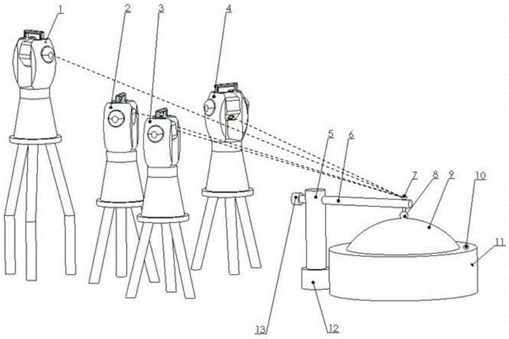
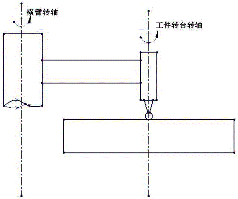
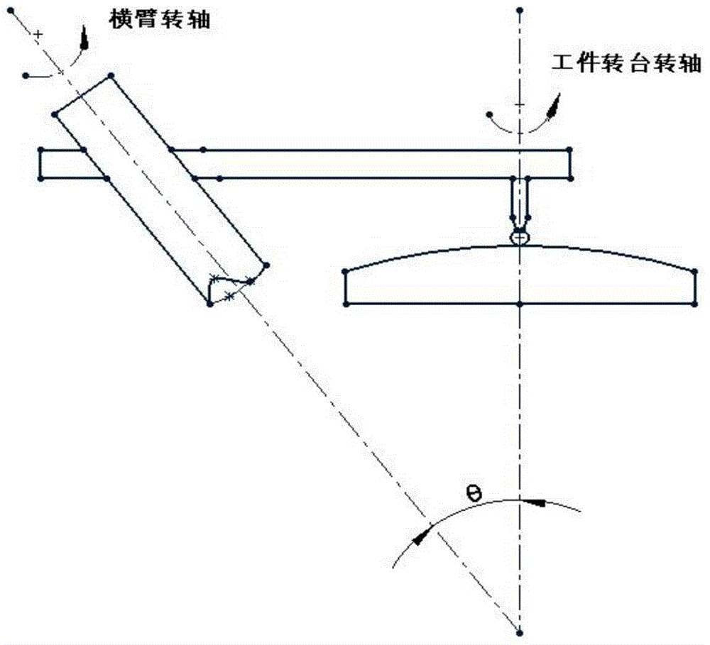
[0017] Such as figure 1 As shown, the equipment for the calibration method of the spatial state of the rotating axis of the swing arm profiler includes: 4 laser trackers 1, 2, 3, 4; cross arm shaft 5; cross arm 6; laser tracker target ball 7; Profilometer measuring head 8; workpiece to be measured 9; peephole 10; workpiece turntable 11; swing arm turntable 12; counterweight 13. in:

[0018] 4 laser trackers 1, 2, 3, 4 respectively track the target ball 7 and the cat's eye 10 of the laser tracker when calibrating the axis of the cross arm and the axis of the workpiece turntable;

[0019] The laser tracker target ball 7 and cat's eye 10 are installed on the cross arm 6 and the workpiece turntable 11 through a spec...


PUM


Abstract

The invention discloses a rotation axis spatial state calibrating method for a swinging arm-type contourgraph. According to the calibrating method, the rotation axis spatial state of the swinging arm-type contourgraph is calibrated by combining a three-side measurement principle with a four-laser tracker redundant self-calibrating technology. A target ball (cat eye) is mounted on a cross arm (workpiece turntable) of the contourgraph; the positions of four laser trackers are fixed, so that the four laser trackers are positioned at the optimal measurement positions. When the cross arm (workpiece turntable) rotates by a certain angle, the four laser trackers track the target ball (cat eye) to perform scanning measurement; a cross arm circular rotating surface (workpiece turntable circular rotating surface) is fit by the acquired three-dimensional coordinates of a point on a high-precision rotating arc to obtain a normal vector which passes through a circle center; the rotation axis spatial state relationship of the swinging arm-type contourgraph can be obtained by calculating the spatial state relationship between two normal lines. According to the method, the state relationship of a spatial axis can be calibrated with high precision.

Description

technical field [0001] The invention belongs to the field of instruments and meters, relates to the calibration of the spatial state of the rotating shaft of a swing-arm type profiler, and is suitable for the position calibration and measurement of the spatial rotating axis. Background technique [0002] The swing arm profiler is an effective in-situ inspection instrument for optical mirror processing. Its biggest feature is that it is directly installed next to the optical mirror to be tested, and the turntable of the optical mirror processing machine tool to be tested is used as the swing arm profiler. The working turntable is used for real-time on-site detection of the mirror surface to be tested. The measurement of mirrors with different surface shapes (concave mirror, convex mirror, plane mirror, etc.) by the swing arm profiler is realized by adjusting the spatial position between the axis of the cross arm shaft and the axis of the workpiece shaft (see appendix figure ...

Claims


Application Information

Patent Timeline
Patent Type & Authority Applications(China)
IPC IPC(8): G01B11/00
Inventor 高明星景洪伟陈林李杰范天泉
Owner INST OF OPTICS & ELECTRONICS - CHINESE ACAD OF SCI
Learn More