a pre-oxidizing furnace

A pre-oxidation furnace and furnace body technology, which is applied in the fields of fiber chemical characteristics, textiles and papermaking, etc., can solve the problems of carbon fiber mechanical properties decline, poor sealing of oxidation furnace, and low carbon fiber mechanical properties, so as to improve tensile properties, The effect of reducing mechanical friction damage and uniform pre-oxidation degree

Active Publication Date: 2016-08-10
GUANGZHOU KINGFA CARBON FIBER NEW MATERIALS DEV
View PDF6 Cites 0 Cited by
  • Summary
  • Abstract
  • Description
  • Claims
  • Application Information

AI Technical Summary

Problems solved by technology

Since the double diffusion process of the carbon fiber precursor is from the surface to the inside during solidification into fibers, it has a slight skin-core structure; and the existing pre-oxidation furnace is also carried out from the surface to the inside during the pre-oxidation process, so The pre-oxidation process will intensify the skin-core structure, and the skin-core structure of the pre-oxidized wire will eventually cause the mechanical properties of carbon fibers to gradually decrease from the surface to the inside, and the mechanical properties of carbon fibers are generally lower
[0004] Patent CN201193260Y discloses a pre-oxidation furnace, which is provided with a base, a roller, an exhaust duct, a circulation fan, a return air duct, and an air supply duct. However, this patent mainly solves the problem that the existing oxidation furnace has poor sealing performance and isothermal zone The problem of unevenness, the improvement of the pre-oxidized silk sheath-core structure is not mentioned

Method used


Image

  • a pre-oxidizing furnace
  • a pre-oxidizing furnace

Examples


Embodiment 1

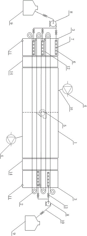
[0024] Such as figure 1 As shown, a pre-oxidation furnace includes a furnace body shell 1, a roller 2 and two furnace end humidifying devices 3, the furnace end humidifying devices 3 are located at both ends of the furnace body shell 1, and the furnace end humidifying device 3 is provided with a humidifying tube 6 for humidifying The pipe 6 is provided with a humidifying hole 7, and the humidifying pipe 6 is connected with the pipeline pump 8 through the connecting pipe 10, and the pipeline pump 8 is connected with the humidification liquid storage tank 9 through the connecting pipe 10, and the connecting pipe 10 is provided with a switching valve 13.

[0025] When in use, the humidifying pipe 6 is located above each layer of tow through the spray humidification method, and the humidifying liquid sprays and humidifies the fibers from top to bottom through the humidifying holes 7 .

[0026] The humidification tubes 6 are separated by partitions 12 , and the bottom of the partit...

Embodiment 2

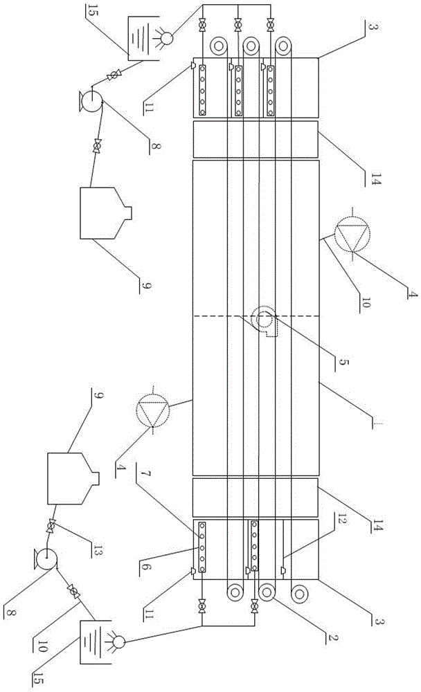
[0030] Such as figure 2 As shown, a pre-oxidation furnace includes a furnace body shell 1, a roller 2 and two furnace end humidifying devices 3, the furnace end humidifying devices 3 are located at both ends of the furnace body shell 1, and the furnace end humidifying device 3 is provided with a humidifying tube 6 for humidifying The tube 6 is provided with a humidifying hole 7, the humidifying tube 6 is connected to the ultrasonic nebulizer 15 through the connecting pipeline 10, the ultrasonic nebulizer 15 is connected to the pipeline pump 8 through the connecting pipeline 10, and the pipeline pump 8 is connected to the humidifying liquid storage through the connecting pipeline 10. Tank 9 is connected.

[0031] A partition 12 is arranged between each humidifying tube, and a waste liquid discharge port 11 is provided at the bottom of the partition 12 and the furnace end humidifier 3 , and the residual humidifying liquid can be gradually discharged through the waste liquid dis...


PUM


Abstract

The invention discloses a pre-oxidation furnace, which comprises a furnace shell, a roller, a circulation fan and an exhaust fan. The circulation fan and the exhaust fan are connected to the furnace shell through connecting pipes. Furnace-side humidifying device, the inside of the furnace-end humidifying device is provided with a humidifying pipe, and a humidifying hole is arranged on the humidifying pipe, and the humidifying pipe is connected with a humidifying liquid storage tank through a connecting pipe. The present invention is equipped with furnace end humidification devices at both ends of the pre-oxidation furnace, which can greatly reduce the mechanical friction damage of carbon fibers and greatly reduce the amount of wool on the surface of carbon fibers during the pre-oxidation production process. The obtained pre-oxidized wire basically has no skin-core structure or has a very slight skin-core structure. The tensile strength and tensile elastic modulus of the carbon fiber prepared by carbonizing the pre-oxidized wire are greatly improved, and the carbon fiber is not easy to break.

Description

technical field [0001] The invention relates to the field of carbon fiber production equipment, in particular to a pre-oxidation furnace. Background technique [0002] In the middle and late 20th century, carbon fiber began to be widely used in aerospace, sporting goods and other fields due to its excellent performance as a fiber-reinforced composite material. The carbon fiber manufacturing process includes pre-oxidation, carbonization, surface treatment and other steps, and each step has an important impact on the quality of carbon fiber. High-performance, high-quality carbon fiber requires the performance of the product to maintain good uniformity and stability. For the production of high-performance carbon fibers, the performance and uniformity of raw materials in the production process, the production conditions of each step of pre-oxidation and carbonization, and the stability of production equipment all directly determine the final performance of carbon fiber products...

Claims


Application Information

Patent Timeline
Patent Type & Authority Patents(China)
IPC IPC(8): D01F9/12
Inventor 黄险波陈大华雷震宋威蔡彤旻
Owner GUANGZHOU KINGFA CARBON FIBER NEW MATERIALS DEV
Why Eureka
Try Eureka