Full-automatic winding device and winding displacement control method thereof

A technology of winding device and control method, which is applied in the control field of automatic winding device and wire arrangement of automatic winding device, can solve the problem of uncontrollable number of coils of wire rod, and achieve the effect of eliminating the gap in wedge-shaped area

Active Publication Date: 2015-06-03
XIAN TELISON NEW MATERIAL
View PDF7 Cites 4 Cited by
  • Summary
  • Abstract
  • Description
  • Claims
  • Application Information

AI Technical Summary

Problems solved by technology

[0003] For this reason, the present invention provides a control method and a fully automatic winding device for fully automatic winding device wiring control, which solves the problem of producing milliseconds at the moment of reversing, which is easy to occur in the prior art when the fully automatic winding device is controlled. The stagnation within the level and the uncontrollable technical problem of the number of turns of the wire wound on each layer of the reel shaft

Method used


Image

  • Full-automatic winding device and winding displacement control method thereof
  • Full-automatic winding device and winding displacement control method thereof
  • Full-automatic winding device and winding displacement control method thereof

Examples


Embodiment 1

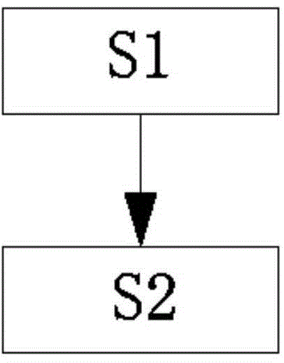
[0049] Without loss of generality, figure 2 As shown, the present invention provides a method for controlling the wiring of a fully automatic winding device after a deep analysis of the reasons for the technical problem that the number of turns at both ends of the material tray is prone to be uncontrollable during automatic winding. , divided into the following steps:

[0050] S1. Calculate the time t used by the traversing axis of the automatic winding device for each traversing distance L; the unit of t is seconds, and L is the sum of the wire width and the wire gap, and the wire gap is located on the same material tray axis, the same The axial gap between two adjacent coils of wire in the wire layer;

[0051] S2. Split t into t 1 and t 2 , t=t 1 +t 2 ; When the first servo motor receives the commutation pulse signal every time, delay t 1 The length of time to send a pulse signal to the first servo motor, and at t 1 At the end of the time, the duration of sending to ...

Embodiment 2

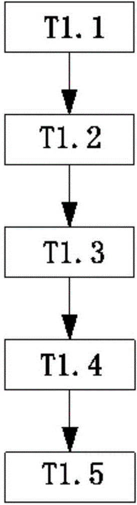
[0063] In order to further solve the technical problem that the automatic winding device is prone to wedge-shaped gaps at both ends of the tray, Figure 4 As shown, on the basis of Embodiment 1, the present invention further fine-tunes the sum L of the wire width and the wire gap, and by fine-tuning the wire gap of each wire layer, the technical effect that each wire layer is fully wound with wire is achieved. In this technical solution, the data of the number of coils of the wire wound on the same wire layer is very large, and the size of the wedge-shaped gap is evenly dispersed on the wire gap, and the technical principle that the gap after fine-tuning can be ignored visually can achieve the above-mentioned technical effect. . The specific operation is as follows:

[0064] S3. Fine-tuning the L until there is no wedge-shaped area on each layer of the wire layer wound on the reel shaft. The effect is to make the existing wedge-shaped area disappear when winding according to ...


PUM


Abstract

The invention provides a full-automatic winding device and a winding displacement control method thereof and solves technical problems that stagnation in the millisecond level is easy to be produced instantly due to reversing and number of turns of wires wound on each layer of workpiece tray shaft is uncontrollable during winding displacement control in the prior art are solved. The method includes the steps of S1, calculating time t spent for a transverse shaft of the full-automatic winding device in transversely moving the distance L; S2, dividing the t into a t1 and t2, wherein t=t1+t2; delaying the time duration of the t1 for transmitting pulse signals to a first servo motor each time the first servo motor receives the reversing pulse signals, and sending the pulse signals of accelerated movement with duration of t2 and frequency of (t*f) / t2 to the first servo motor at the end of the time t1; sending the pulse signals to the first servo motor with frequency of f within the time from the end of the time t2 to the next time that the reversing pulse signals are received by the first servo motor. The full-automatic winding device is controlled automatically by the application of the above method.

Description

technical field [0001] The invention relates to the technical field of automatic control of a fully automatic wire winding device, in particular to a control method for arranging a fully automatic winding device and a fully automatic winding device. Background technique [0002] figure 1 As shown, the fully automatic take-up and pay-off device in the prior art generally includes: a tray shaft 001, a rotating motor 002 for driving the tray shaft to rotate, and a traverse motor 004 for driving the tray shaft 001 to traverse through the traverse shaft 003. The fully automatic take-up and pay-off device in the prior art only utilizes the traverse motor 004 to drive the traverse shaft 003 to achieve reciprocating feed while cooperating with the rotating motor 002 to drive the feeder shaft 001 to rotate, so that the wire can be easily made on the feeder shaft 001. Reciprocating motion, and then realize the accumulation of wire materials layer by layer on the material tray shaft 0...

Claims


Application Information

Patent Timeline
IPC IPC(8): B65H54/30B65H63/00
Inventor 李进董文卫罗航
Owner XIAN TELISON NEW MATERIAL
Why Eureka
Try Eureka