
Bogie frame structure for traveling system of paver

The technology of a traveling system and a trolley frame is applied in the field of road machinery and equipment, and can solve the problems of inconsistent machining datums of the mounting plate and the mounting plate hole on the side of the body, difficulty in assembling the trolley frame and the paver frame, and the assembling of the trolley frame. There are many problems such as welding parts, so as to achieve the effect of easy guarantee of welding quality, convenient assembly and welding, and reasonable and beautiful layout of hydraulic oil pipes

Active Publication Date: 2015-06-03
柳工无锡路面机械有限公司
View PDF7 Cites 0 Cited by
  • Summary
  • Abstract
  • Description
  • Claims
  • Application Information

AI Technical Summary

Problems solved by technology

[0003] At present, the conventional trolley frame generally includes a reducer mounting seat, a guide wheel mounting seat, a body upper mounting plate, a body side mounting plate, side plates, left and right beam plates and rib plates, etc., as disclosed in Chinese patent ZL201110393820.8 " A trolley frame" or similar structure used for the walking system of a crawler-type multifunctional paver. The trolley frame of this type of structure has many welded parts, large welding deformation, and difficult to control the welding quality; at the same time, the mounting plate and The machining standard of the mounting plate hole on the side of the main body is not uniform, and it needs to be turned frequently. The machining is difficult and the machining accuracy is difficult to guarantee, which makes the assembly of the trolley frame and the paver frame difficult, which is not conducive to alignment assembly, and seriously affects the paving after assembly. machine construction quality

Method used


Image

  • Bogie frame structure for traveling system of paver
  • Bogie frame structure for traveling system of paver
  • Bogie frame structure for traveling system of paver

Examples


Embodiment Construction

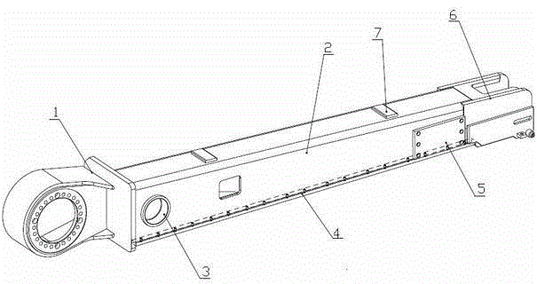
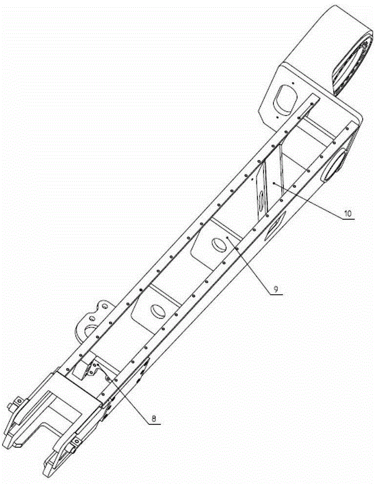
[0022] see Figure 1~6 , the present invention relates to a trolley frame structure for a paver walking system, the structure includes a box bending plate 2, the box bending plate 2 is an inverted groove structure, and the box bending plate 2 The top surface of the box is set along its length as an inclined plane, one end of the box bending plate 2 is connected with the reducer mounting seat 1, and the other end is connected with the guide wheel mounting seat 6, and the speed reducer mounting seat 1 and the box bending plate 2 The connection is located at the high position of the top slope of the box bending plate 2, and the connection between the guide wheel mounting seat 6 and the box bending plate 2 is located at the low position of the top slope of the box bending plate 2, and the box is set in an inverted groove shape. Bottoms of the two side plates of the body curved plate 2 are equipped with strip-shaped bottom plates 4; the top slope of the box body curved plate 2 is p...


PUM


Abstract

The invention relates to a bogie frame structure for a traveling system of a paver. The bogie frame structure comprises a box bend plate (2), and a speed reducer mounting seat (1) is connected to one end of the box bend plate (2) while a guide wheel mounting seat (6) is connected to the other end of the box bend plate (2). A hinge pin sleeve (3) is penetratingly connected to one end, close to the speed reducer mounting seat (1) of each of two side plates of the box bend plate (2). A mounting plate (5) is arranged at one end, close to the guide wheel mounting seat (6), of each of two side plates of the box bend plate (2) and provided with a plurality of screw holes. The bogie frame structure for the traveling system of the paver has the advantages of simple structure, low cost, convenience in machining, easiness in assembly and attractive appearance.

Description

technical field [0001] The invention relates to a trolley frame structure, in particular to a trolley frame structure used on the walking system of a crawler paver, and belongs to the technical field of road surface machinery equipment. Background technique [0002] As the basic structural part of the paver (especially crawler paver) walking system, the trolley frame is the main force-bearing part in the paver. It bears the weight from the whole machine and the paving materials. Walking is realized by the travel drive motor and reducer drive sprocket installed at the rear of the trolley frame. Therefore, whether the structural form of the trolley frame is reasonable or not and whether the trolley frame and the chassis can be assembled directly affect the structure of the whole machine. and the stability of walking work, thus affecting the construction quality of the paver; [0003] At present, the conventional trolley frame generally includes a reducer mounting seat, a guid...

Claims


Application Information

Patent Timeline
Patent Type & Authority Applications(China)
IPC IPC(8): B62D55/10E01C19/12
Inventor 付廷辉冯宗军张明年黎培杰王振
Owner 柳工无锡路面机械有限公司
Learn More