A flat graphic printer

A printer, graphic technology, applied in the directions of printing, transfer materials, power transmission devices, etc., can solve the problems of small scope of application, inability to print workpieces, etc., to achieve the effect of accurate positioning, small vibration, and improved service life

Inactive Publication Date: 2017-02-08
ZHENGZHOU LECAI SCI & TECH
View PDF7 Cites 0 Cited by
  • Summary
  • Abstract
  • Description
  • Claims
  • Application Information

AI Technical Summary

Problems solved by technology

[0004] However, in the above-mentioned flat graphic printer, the X table is used to support the workpiece, and the nozzle is only arranged on the beam through the beam, and the nozzle can only move in the vertical direction. In order to ensure that the entire range of the workpiece can be printed, When working, the workpiece needs to move with the X workpiece table on the table of the fuselage, that is, the table of the fuselage has a size margin for the movement of the workpiece, which makes the existing flat graphic printer unable to print the workpiece with too large size, and the scope of application is small

Method used


Image

  • A flat graphic printer
  • A flat graphic printer
  • A flat graphic printer

Examples


Embodiment Construction

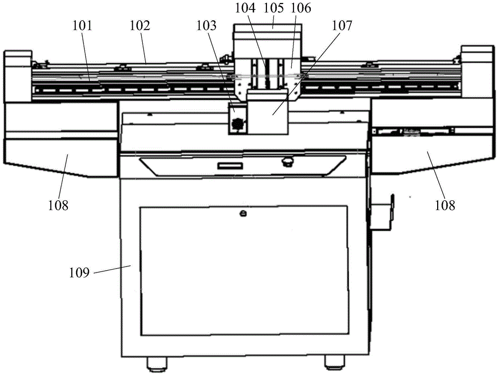
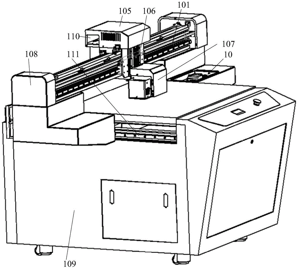
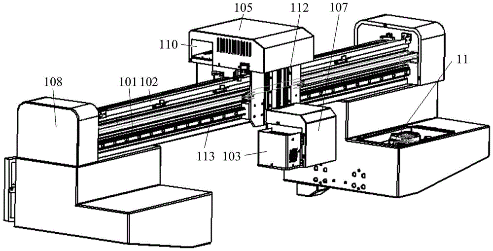
[0036] The embodiment of the invention discloses a flat image-text printer, in which only the position of the nozzle is adjusted after the sliders on each workbench are moved, which can avoid moving the workpiece during the spray printing process, and is suitable for workpieces of various sizes.

[0037] The following will clearly and completely describe the technical solutions in the embodiments of the present invention with reference to the accompanying drawings in the embodiments of the present invention. Obviously, the described embodiments are only some, not all, embodiments of the present invention. Based on the embodiments of the present invention, all other embodiments obtained by persons of ordinary skill in the art without making creative efforts belong to the protection scope of the present invention.

[0038] see Figure 1-Figure 3 , the planar graphic printer provided by the embodiment of the present invention includes: a body 109, a Y workbench, an X workbench 10...


PUM


Abstract

The invention discloses a planar image-text printer. The planar image-text printer comprises a body, a Y worktable, an X worktable and a Z worktable, wherein the body can be used for supporting to-be-printed workpieces; the Y worktable is fixed on the body; a first sliding rail with a Y sliding block is paved on the Y worktable; the X worktable is fixed on the Y sliding block; a second sliding rail with an X sliding block is paved on the X worktable; the Z worktable is fixed on the X sliding block; a third sliding rail with a Z sliding block is paved on the Z worktable; a nozzle is fixed on the Z sliding block. In the planar image-text printer, the sliding blocks move in an X-axis direction, a Y-axis direction and a Z-axis direction to respectively change the position of the nozzle; the workpieces are just arranged on a platform of the body in the using process; the movement of the workpieces is avoided and the allowance for moving the workpieces on the platform of the body is reduced, so that the planar image-text printer is suitable for large-sized workpieces which are even as large as the platform, and is wide in range of application.

Description

technical field [0001] The present invention relates to the technical field of printing equipment, and more specifically, relates to a plane image-text printer. Background technique [0002] Flat graphic printers are mainly used for graphic printing on the surface of PCB (Printed Circuit Board, printed circuit board). [0003] Existing graphic printers include a fuselage, an X workbench, a Y workbench and a Z workbench, wherein the Y workbench is set on the table top of the fuselage to be able to move along the first straight line through slide rails; the X workbench The table is set on the Y worktable so that it can move along the second linear direction through the slide rail; the Z workbench is arranged on the crossbeam, and the crossbeam is fixed on the fuselage; the Z workbench is provided with a slider that can move in the vertical direction , the nozzle is fixed on the slider; the above-mentioned first straight line and second straight line are both horizontal and pe...

Claims


Application Information

Patent Timeline
Patent Type & Authority Patents(China)
IPC IPC(8): B41J2/01B41J25/304
Inventor 王纪伟乔学生张存山
Owner ZHENGZHOU LECAI SCI & TECH
Why Eureka
Try Eureka