A material cutting mechanism

A material and cutting technology, applied in the field of material cutting mechanism, can solve the problems of high labor cost, low production efficiency, small size of material, etc., to reduce labor intensity, improve production efficiency, and high cutting precision. Effect

Active Publication Date: 2016-05-25
BOZHON PRECISION IND TECH CO LTD
View PDF10 Cites 0 Cited by
  • Summary
  • Abstract
  • Description
  • Claims
  • Application Information

AI Technical Summary

Problems solved by technology

[0002] In the IT industry, it is necessary to cut various components to meet the processing needs of different equipment. Due to the small size of the material, ordinary cutting machines cannot meet the cutting accuracy requirements, and the most widely used cutting The machine is usually operated manually, and operators are required to carry out hand-held cutting during the cutting process. This cutting method has the following disadvantages: (1) It uses more labor, and after a long time of operation, people will appear Fatigue, lack of concentration lead to personal injury, there are certain potential safety hazards, low production efficiency, and high labor costs; (2) Sometimes the positioning of the product is not accurate, resulting in the phenomenon of product cutting errors. At the same time, manual operation cannot Accurately control the cutting force, the cutting accuracy is not high, and the labor intensity of the operators is high, so it is not suitable for automatic production on the assembly line

Method used


Image

  • A material cutting mechanism
  • A material cutting mechanism

Examples


Embodiment

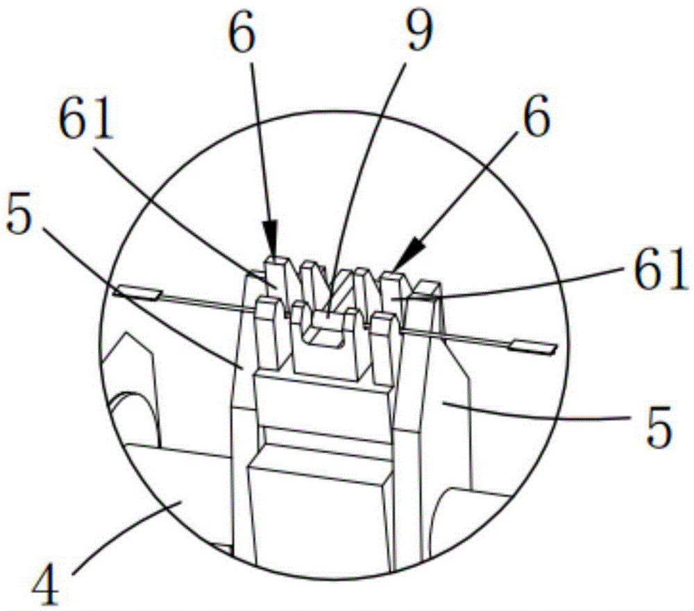
[0019] like figure 1 As shown, a material cutting mechanism includes a support mechanism 1, a pulling mechanism 2, a connecting rod 3, a rotating shaft 4, a cutting knife mold a5 and a cutting knife mold b6, and a support mechanism 1 is horizontally provided plate 7, and the lifting mechanism 2 is vertically fixed on the end of the support plate 7, and placed on the front side of the support mechanism 1; the upper end surface of the support mechanism 1 is provided with a fixing seat 11, and the left and right sides of the fixing seat 11 are respectively A support 8 is vertically provided, and the support 8 is provided with a shaft hole adapted to the rotating shaft 4, and the rotating shaft 4 is rotated and arranged on the support 8; the cutting die a5 and the cutting die b6 are respectively set On the rotating shaft 4, the cutting knife mold b6 is vertically fixed on the fixed seat 11, and the cutting knife mold a5 is placed on the left and right sides of the cutting knife mo...


PUM


Abstract

The invention relates to a material cutting mechanism, which comprises a support mechanism, a lifting mechanism, a connecting rod, a rotary shaft, cutting tool dies a and cutting tool dies b, wherein the lifting mechanism is arranged at the front side of the support mechanism, a fixing seat is arranged at the upper end surface of the support mechanism, brackets are respectively and vertically arranged at the left side and the right side of the fixing seat, the rotary shaft is rotationally arranged on the brackets, the cutting tool dies a and the cutting tool dies b respectively sleeve the rotary shaft, the cutting tool dies a are arranged at the left sides and the right sides of the cutting tool dies b and are fixedly connected with the rotary shaft, the connecting rod is in an L shape, one end of the connecting rod is fixedly connected with the rotary shaft, the other rend of the connecting rod is hinged to the top end of the lifting mechanism, and the lifting mechanism moves up and down to drive the cutting tool dies a on the rotary shaft to cut the material through the connecting rod. The material cutting mechanism has the advantages that the lifting mechanism moves up and down to drive the cutting tool dies a on the rotary shaft to cut the material through the connecting rod, so the materials with different sizes can be cut by the whole mechanism, the production efficiency is greatly improved, the cost is reduced, and the labor intensity of operators is decreased.

Description

Technical field: [0001] The invention relates to the field of mechanical processing, and more specifically relates to a material cutting mechanism. Background technique: [0002] In the IT industry, it is necessary to cut various components to meet the processing needs of different equipment. Due to the small size of the material, ordinary cutting machines cannot meet the cutting accuracy requirements, and the most widely used cutting The machine is usually operated manually, and operators are required to carry out hand-held cutting during the cutting process. This cutting method has the following disadvantages: (1) It uses more labor, and after a long time of operation, people will appear Fatigue, lack of concentration lead to personal injury, there are certain potential safety hazards, low production efficiency, and high labor costs; (2) Sometimes the positioning of the product is not accurate, resulting in the phenomenon of product cutting errors. At the same time, manual...

Claims


Application Information

Patent Timeline
Patent Type & Authority Patents(China)
IPC IPC(8): B26F1/38B26F1/44
CPCB26D5/08B26F1/38B26F1/44
Inventor 吕绍林杨愉强王建福张杰
Owner BOZHON PRECISION IND TECH CO LTD
Why Eureka
Try Eureka