Optical fiber manufacturing method

A manufacturing method and optical fiber technology, which is applied in the field of optical fiber manufacturing, can solve problems such as productivity degradation, slow drawing speed, and long slow cooling time, and achieve the effects of lower fictive temperature, high productivity, and low loss

Active Publication Date: 2017-09-19
SUMITOMO ELECTRIC IND LTD
View PDF1 Cites 0 Cited by
  • Summary
  • Abstract
  • Description
  • Claims
  • Application Information

AI Technical Summary

Problems solved by technology

Therefore, this conventional slow cooling technique may not sufficiently reduce the attenuation in the optical fiber, and may deteriorate productivity because the furnace for slow cooling may be longer than necessary, or to ensure a longer The slow cooling time, the drawing speed may be slower

Method used


Image

  • Optical fiber manufacturing method
  • Optical fiber manufacturing method
  • Optical fiber manufacturing method

Examples


Embodiment Construction

[0025] Embodiments of the present invention will now be described in more detail with reference to the accompanying drawings. In the description of the drawings, the same reference numerals are given to the same components, and repeated descriptions are omitted.

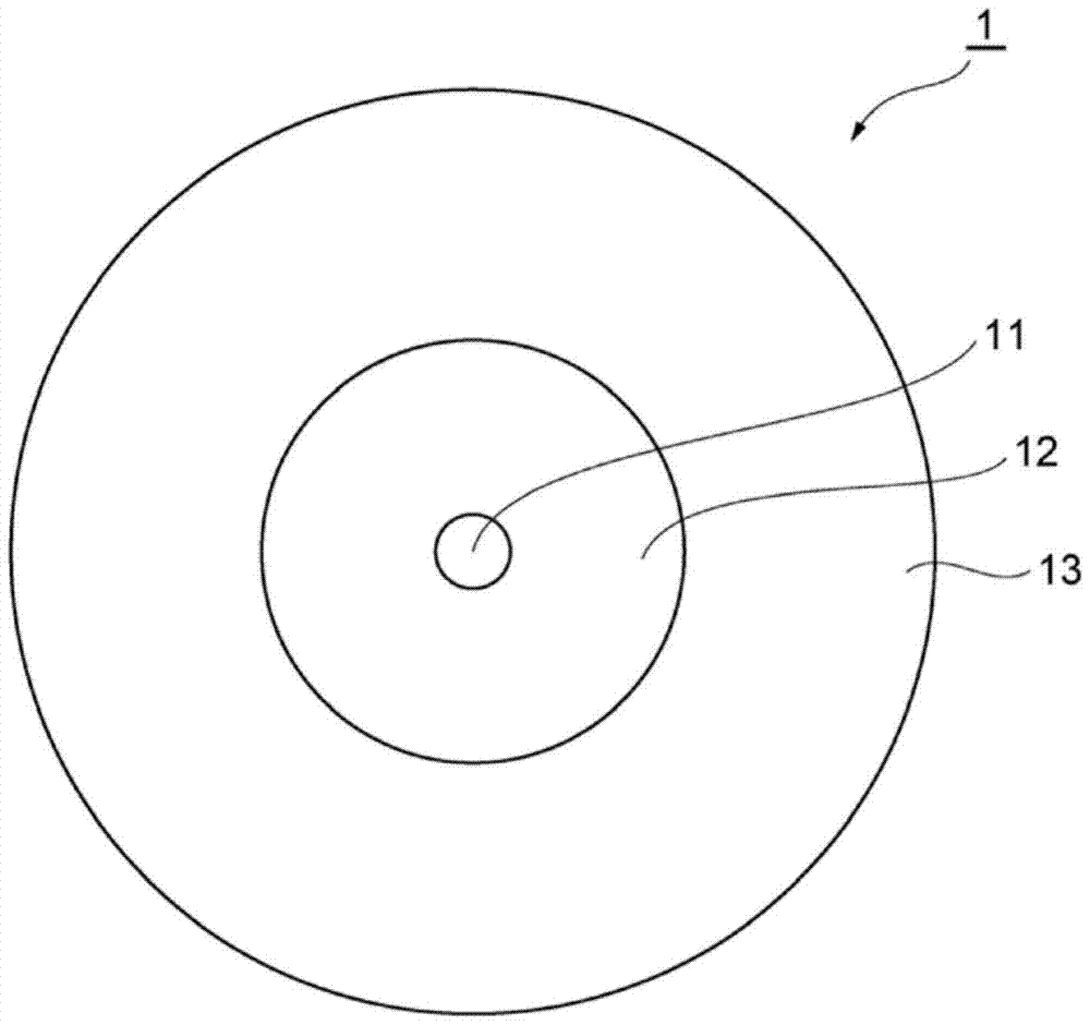
[0026] figure 1 is a cross-sectional view of an optical fiber 1 according to the invention. The optical fiber 1 is a silica-based optical fiber, and includes a central core 11 having a central axis, an optical cladding 12 surrounding the central core 11 , and a sheath 13 surrounding the optical cladding 12 .

[0027] The relative refractive index differences of the central core 11 and the sheath 13 with respect to the refractive index of the optical cladding 12 are described respectively. The refractive index of the central core 11 is described as an equivalent step index (ESI). The outer diameter of the optical cladding 12 is defined as the diameter at which the difference in the radial variation of the refractiv...


PUM

PropertyMeasurementUnit
areaaaaaaaaaaa
areaaaaaaaaaaa

Abstract

An optical fiber manufacturing method includes a drawing step and a slow cooling step. In said slow cooling step, the optical fiber passes through a heating furnace whose temperature is set such that in at least 70% of the area from the first position to the second position, the actual temperature of the optical fiber is at each position n within ±100°C of the target temperature T(n), wherein the first position is located where the glass outer diameter of the fiber becomes less than 500% of the final outer diameter, and the second position is where the temperature T of the fiber becomes 1400°C place. Said target temperature T(n) is the temperature at which the fictive temperature Tf(n+1) of the core at position n+1 is the lowest, wherein starting from the fictive temperature Tf(0) of the fiber at the first position n=0, by Use the following recursive formula to calculate and determine Tf(n+1): Tf(n+1)=T(n)+(Tf(n)‑T(n))exp(‑Δt / τ(T(n) )).

Description

technical field [0001] The present invention relates to methods of manufacturing optical fibers. Background technique [0002] For high-speed optical communication with a transmission rate above 100 Gbit / s, a high optical signal-to-noise ratio (OSNR) is required. Optical fibers used as optical transmission lines are increasingly required to be low-loss, low-nonlinear optical fibers. Fiber nonlinearity and n 2 / Aeff is proportional, where n 2 is the nonlinear refractive index of the fiber, and Aeff is the effective area of ​​the fiber. The larger the effective area Aeff, the more likely it is to reduce the concentration of light energy to the core, and thereby reduce the nonlinearity. The effective area Aeff of a standard single-mode fiber conforming to ITU-T G.652 at a wavelength of 1550nm is about 80μm 2 . However, it is preferred that the effective area Aeff of the low nonlinear fiber is within 100 μm 2 to 180μm 2 In the range. [0003] Larger effective area Aeff ...

Claims


Application Information

Patent Timeline
Patent Type & Authority Patents(China)
IPC IPC(8): C03B37/027
CPCC03B37/02727C03B2205/56C03B2205/72C03B2201/31C03C25/002C03C25/607C03B2205/55C03B2203/22C03B37/0253C03B37/02718G02B6/10
Inventor 中西哲也小西达也桑原一也
Owner SUMITOMO ELECTRIC IND LTD
Why Eureka
Try Eureka