
An FPGA-based optical fiber to fully configured camera link real-time image optical transceiver

A real-time image, full-configuration technology, applied in TV systems adapted to optical transmission, cable transmission adaptation, closed-circuit TV systems, etc., can solve the problem of poor anti-interference of Cameralink cables, failure to meet long-distance transmission, and failure to meet transmission requirements and other problems, to achieve the effect of improving stability and reliability, enhancing anti-electromagnetic interference ability, and simplifying wiring complexity

Active Publication Date: 2018-02-13
INST OF OPTICS & ELECTRONICS - CHINESE ACAD OF SCI
View PDF6 Cites 0 Cited by
  • Summary
  • Abstract
  • Description
  • Claims
  • Application Information

AI Technical Summary

Problems solved by technology

[0002] In the traditional Camera link image transmission system, the transmission medium between devices is directly connected by Cameralink cable. Due to the poor anti-interference performance of the Camera link cable and the short transmission distance (less than 10 meters), it cannot meet the long-distance requirements. distance transmission
In recent years, with the development of optical fiber interconnection transmission technology, basic (Base) Camera link image optical transceivers based on optical fiber transmission have gradually appeared, but they can only realize basic (Base) Camera link image transmission, and the transmission distance is short (about 300 meters), which fail to meet the long-distance transmission of long-distance camera link real-time images with medium configuration (Medium), full configuration (Full), and high bandwidth (85MHz) for engineering needs, and fail to meet the transmission of longer distances (100 kilometers and above) need

Method used


Image

  • An FPGA-based optical fiber to fully configured camera link real-time image optical transceiver
  • An FPGA-based optical fiber to fully configured camera link real-time image optical transceiver

Examples


Embodiment Construction

[0052] The present invention will be further described below in conjunction with the embodiments and accompanying drawings.

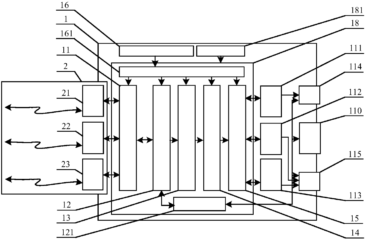
[0053] The present invention adopts the attached figure 1 The optical fiber to Camera link device (1), SFP optical fiber interconnection transmission device (2), and an application example of a fiber to fully configured Camera link real-time image optical terminal is built.

[0054] The SFP optical fiber interconnection channel 1 (21) of the SFP optical fiber interconnection transmission device (2) is interconnected with the SFP optical fiber interconnection channel 1 of the Camera link to optical fiber device through an optical fiber cable; the SFP optical fiber interconnection channel 2 (22) is connected with the Cameralink through an optical fiber cable The SFP optical fiber interconnection channel 2 of the optical fiber conversion device is interconnected; the SFP optical fiber interconnection channel 3 (23) is interconnected with the SFP optical fi...


PUM


Abstract

An FPGA-based optical fiber to fully configured Camera link real-time image optical transceiver, which realizes the conversion function of optical fiber real-time image input to high-bandwidth (85MHz) and high-reliability full-configuration (Full) Camera link real-time image output, and has Full configuration (Full), medium (Medium) or basic (Base) Camera link self-adaptive configuration function of real-time image output, self-adaptive function of Camera link output working frequency, and realizes serial port data and timing synchronization control of Camera link The conversion function of signal input to optical fiber data stream output extends the communication distance of the serial port and timing control signal of Camera link; the design provides flexible configuration of SFP optical fiber module, and the transmission distance is from 500 meters to 120 kilometers, which improves the real-time performance of Camera link The stability and reliability of image transmission enhances the anti-electromagnetic interference capability of Camera link real-time image transmission and meets the needs of various engineering applications.

Description

technical field [0001] The present invention relates to high-bandwidth (85MHz), high-reliability full-configuration (Full) Camera link real-time image long-distance transmission, in particular to a Camera link high-speed real-time image remote transmission based on FPGA (Field Programmable Gate Array, Field Programmable Gate Array) Distance transmission is realized. Background technique [0002] In the traditional Camera link image transmission system, the transmission medium between devices is directly connected by Cameralink cable. Due to the poor anti-interference performance of the Camera link cable and the short transmission distance (less than 10 meters), it cannot meet the long-distance requirements. distance transmission. In recent years, with the development of optical fiber interconnection transmission technology, basic (Base) Camera link image optical transceivers based on optical fiber transmission have gradually appeared, but they can only realize basic (Base) ...

Claims


Application Information

Patent Timeline
Patent Type & Authority Patents(China)
IPC IPC(8): H04N7/18H04N7/22
Inventor 孙科林蒋平吴钦章苏海冰曹晓伟
Owner INST OF OPTICS & ELECTRONICS - CHINESE ACAD OF SCI
Learn More