
Mobile blanking frame of automatic receiving system

A blanking and automatic technology, applied in the field of mobile blanking racks, can solve the problems of time-consuming and laborious, waste of copper materials, insufficient pressure of the flat winding head, etc., to achieve the effect of expanding the range of processing technology, reducing coil deformation, and improving the efficiency of flat winding

Inactive Publication Date: 2015-05-27
TIANJIN TIRNFR HEAVY HYDROELECTRIC FRCILITY CO LTD
View PDF0 Cites 0 Cited by
  • Summary
  • Abstract
  • Description
  • Claims
  • Application Information

AI Technical Summary

Problems solved by technology

[0002] At present, when the special SKBR CNC edge winding machine is used to edge-wind the coil, because the edge-winding head is partially suspended on the working beam of the cantilever-type leveling mechanism, the strength of the cantilever-type leveling mechanism is low, and the pressure of the edge-winding head is insufficient. The outgoing magnetic pole coil has wrinkles and ripples in the turns at the bend, causing damage to the coil
The design of the mobile blanking frame workbench of the automatic material receiving system designed by this equipment is: every time a magnetic pole coil is wound flat, the operator needs to loosen the set screw and screw pin of the material receiving guide rod mounting seat, and according to the winding coil The size of the length and width, symmetrically move the mounting seat and the width adjustment rod, so that the material receiving guide rod is located at the center of the four rounded corners of the coil to be wound, that is, the adjustment of the material receiving tray is completed. This operation is time-consuming and laborious, and increases the operation. The labor intensity of the operator, there is no design lifting function, the first few turns of the flat-wound coil have a large sagging deformation, and a large amount of copper material is wasted

Method used


Image

  • Mobile blanking frame of automatic receiving system

Examples


Embodiment Construction

[0015] The present invention will be described in detail below in conjunction with the accompanying drawings.

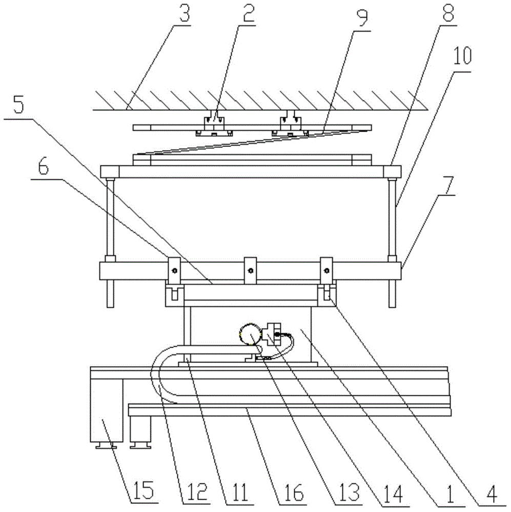
[0016] Such as figure 1 As shown, a mobile blanking frame of an automatic material receiving system of the present invention includes a mounting base 1, a flat winding head 2, a working beam 3 and a vertical support 4, and the working beam 3 is provided with a flat winding head 2, A mounting seat 1 is provided below the flat winding head 2, a vertical support 4 is provided on the mounting seat 1, a slideway 5 is provided on the vertical support 4, and a sliding U-shaped slideway 5 is provided on the slideway 5. Fixture support 6, the sliding U-shaped fixture support 6 is provided with a double-sided guide rail 7, a material-receiving frame 8 is arranged above the double-side guide rail 7, and a material-receiving frame 8 is arranged between the flat winding head 2 and the material-receiving frame 8 There is a magnetic pole coil 9, a screw lifting mechanism 10 is set...


PUM


Abstract

The invention provides a mobile blanking frame of an automatic receiving system. The mobile blanking frame of the automatic receiving system comprises an installing base, an edgewise winding machine head, a working cross beam and a vertical bracket; the working cross beam is provided with the edgewise winding machine head; the installing base is installed below the edgewise winding machine head; the installing base is provided with the vertical bracket; the vertical bracket is provided with a slide rail; the slide rail is provided with a slide U-type clamp supporter; the slide U-type clamp supporter is provided with a double sided guide rail; a receiving frame is installed above the double sided guide rail; a pole coil is installed between the edgewise winding machine head and the receiving frame; and a screw rod lifting mechanism is installed between the double sided guide rail and the receiving frame. The mobile blanking frame of the automatic receiving system is convenient to operate, uses the screw rod lifting mechanism, and has good universality; and the travel is not limited, so the operator can set on a touch screen operation box directly, and the processing craft range of the device is enlarged.

Description

technical field [0001] The invention belongs to the technical field of edge winding machines, and in particular relates to a mobile blanking frame of an automatic material receiving system. Background technique [0002] At present, when the special SKBR CNC edge winding machine is used to edge-wind the coil, because the edge-winding head is partially suspended on the working beam of the cantilever-type leveling mechanism, the strength of the cantilever-type leveling mechanism is low, and the pressure of the edge-winding head is insufficient. The outgoing magnetic pole coil has wrinkles and ripples in the turns at the bend, causing damage to the coil. The design of the mobile blanking frame workbench of the automatic material receiving system designed by this equipment is: every time a magnetic pole coil is wound flat, the operator needs to loosen the set screw and screw pin of the material receiving guide rod mounting seat, and according to the winding coil The size of the ...

Claims


Application Information

Patent Timeline
Patent Type & Authority Applications(China)
IPC IPC(8): H01F41/04H02K15/04
Inventor 路春玲李卫红张跃
Owner TIANJIN TIRNFR HEAVY HYDROELECTRIC FRCILITY CO LTD
Learn More