
Lockable reversing valve

A reversing valve with lock technology, which is applied in the direction of fluid pressure actuators, servo motor components, mechanical equipment, etc., can solve the problems of increasing the difficulty of valve body casting, reducing operating comfort, increasing operating force, etc., to achieve convenient Processing, ensuring the comfort of operation, and the effect of small changes

Active Publication Date: 2015-05-27
四川长江液压件有限责任公司
View PDF6 Cites 2 Cited by
  • Summary
  • Abstract
  • Description
  • Claims
  • Application Information

AI Technical Summary

Problems solved by technology

Traditionally, the simplest solution to ensure static settlement is to control the internal leakage of the valve and reduce the fit gap between the slide valve and the valve body. However, in order to ensure the reset of the slide valve, the operating force needs to be increased, which reduces the operating comfort; the other is no leakage. The solution is to increase the hydraulic control one-way lock, but this solution will increase the difficulty of casting the valve body, the cost is high, and it has no commonality with the general working valve body

Method used


Image

  • Lockable reversing valve
  • Lockable reversing valve
  • Lockable reversing valve

Examples


Embodiment Construction

[0017] The present invention will be described in further detail below in conjunction with the accompanying drawings.

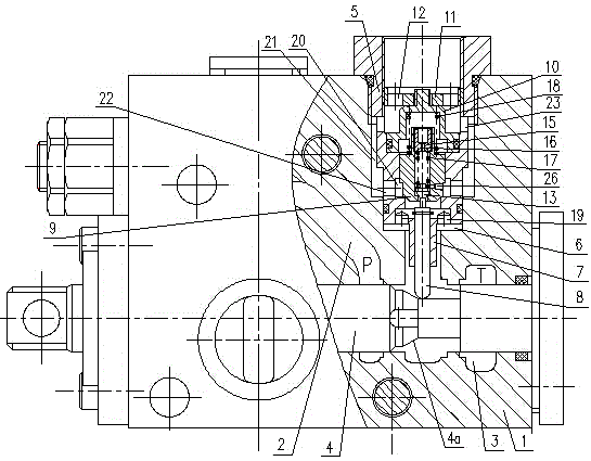
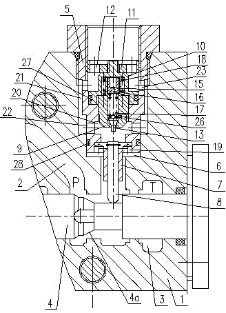
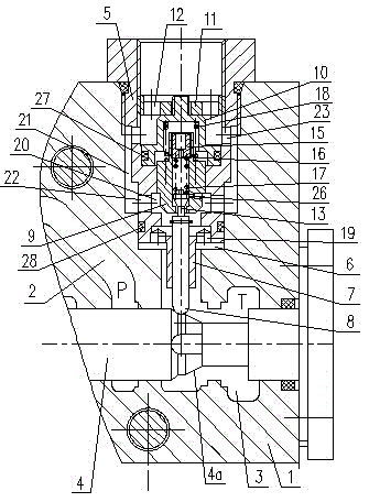
[0018] Such as Figure 1 to Figure 3 As shown, the reversing valve with lock includes a valve body 1, an oil inlet 2 located in the valve body 1, an oil return port 3, two working oil ports and a slide valve 4, and passes through one of the working oil ports 6 The thread is equipped with a valve sleeve 5 with an inner hole, and the end of the valve sleeve 5 close to the slide valve 4 is provided with a guide sleeve 7 which is set in a radial gap with the front end of the working oil port, and a push rod 8 is provided for sliding in the guide sleeve 7 , the slide valve 4 between the push rod 8 and the oil inlet 2 is provided with a gradually rising conical surface 4a; a valve core 9 is provided sliding in the valve sleeve 5 above the push rod 8, and above the valve core 9 A limit seat 10 is provided in the valve sleeve 5, and a limit screw plug 11 in contact ...


PUM


Abstract

The invention discloses a lockable reversing valve. A valve sleeve with a bore is mounted in at least one working oil port of a valve body, one end, which is close to a slide valve, of the valve sleeve is provided with a guide sleeve, a push rod is arranged in the guide sleeve, and the slide valve is provided with a conical surface between the push rod and an oil inlet; a spool is arranged in the valve sleeve over the push rod, a limit seat is arranged in the valve sleeve over the spool, a pilot spool is arranged in the bore of the lower part of the spool, a pilot valve restoring spring is arranged between the pilot spool and the upper end of the spool, and a restoring spring is arranged between the spool and the limit eat; the valve sleeve is provided with an axial hole, an oil cavity is arranged in the valve sleeve outside the spool, an annular cavity is arranged between the middle section of the valve sleeve and the valve body, a lower radial hole and an upper radial hole are arranged in the valve sleeve, and a radial damping hole is arranged in the spool. When the slide valve needs to be restored, control force does not need to be increased, and thereby controlling comfort and no leakage are ensured; moreover, the lockable reversing valve is convenient to machine, demount and mount, and is highly universal.

Description

technical field [0001] The invention relates to a reversing valve with a lock, in particular to a reversing valve with a lock used in a hydraulic system of a tractor. Background technique [0002] Tractor is a multi-purpose, high-efficiency, and flexible agricultural machinery. If the corresponding attachments are replaced, it can perform operations such as loosening soil, plowing, and harvesting. Because of its economical applicability, traditional tractors have high cost control, so the performance requirements are not very high, as long as they can be used. At present, people have higher and higher requirements for the performance of tractors, such as operating comfort, safety, etc., which puts forward new requirements for the reversing valve in the hydraulic system of the main engine: on the one hand, it is necessary to solve the control problem of multiple reversing valves On the other hand, solve the static settlement of the lifting cylinder to ensure no leakage. ...

Claims


Application Information

Patent Timeline
Patent Type & Authority Applications(China)
IPC IPC(8): F15B13/02
CPCF15B13/021
Inventor 阳云王夏金王德华吕林其
Owner 四川长江液压件有限责任公司
Learn More