
Mobile and portable strap cutting machine

A shearing machine and a convenient technology, applied in the field of movable and convenient strapping shearing machines, can solve the problems of low work efficiency, self-weight of strapping, easy rust, etc., so as to solve the problems of low efficiency, ensure stable performance and long service life. Effect

Active Publication Date: 2017-12-19
SHANGHAI MEISHAN IRON & STEEL CO LTD
View PDF7 Cites 0 Cited by
  • Summary
  • Abstract
  • Description
  • Claims
  • Application Information

AI Technical Summary

Problems solved by technology

The previous strapping cutter, after a long time of use, the blade is easy to wear, blunt, and there is a gap between the blades, often cutting does not move, resulting in deformation of the strapping, can not be operated normally, affecting the work efficiency and the appearance and packaging quality of the coil , the work is cumbersome
The strap itself is heavy, it is inconvenient to move, the locks are small, the number is large, they are placed randomly, and they are easy to rust in rainy days. Not only the work efficiency is low, but also the working environment and safety of the site will be affected.

Method used


Image

  • Mobile and portable strap cutting machine
  • Mobile and portable strap cutting machine

Examples


Embodiment 1

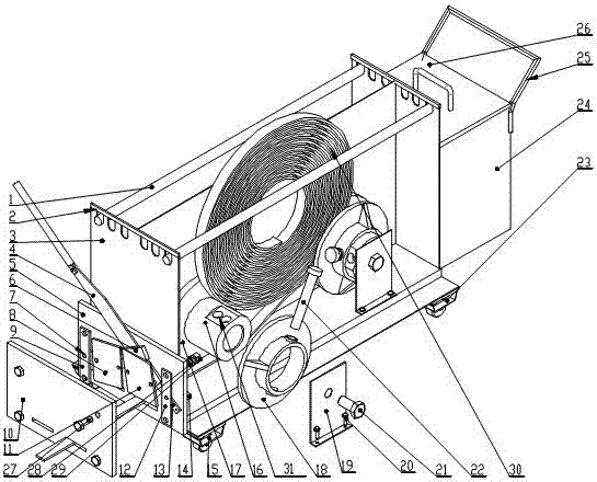
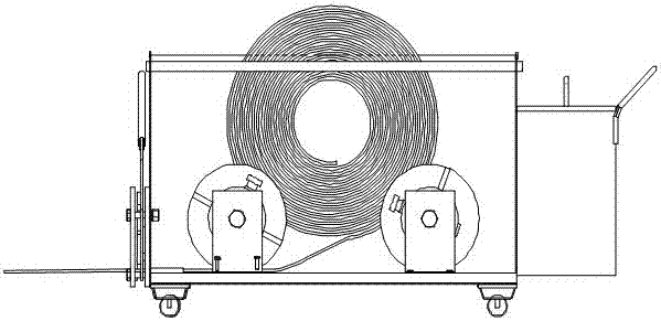
[0020] Such as Figure 1-2 Shown: the mobile and portable strap shearing machine of the present invention includes a main frame, a main frame center plate is installed in the middle of the main frame, and strap fixing adjustment mechanisms are respectively installed on both sides of the main frame center plate A shearing mechanism is installed on one side of the main frame, and storage boxes and handrails are installed on the other side of the main frame.

Embodiment 2

[0022] In the movable and portable strap shearing machine described in Embodiment 1, the shearing frame includes an inner panel welded on the main frame, and a left drive plate and a right drive plate are respectively hinged on the inner panel, and the Both the left transmission plate and the right transmission plate are connected to the operating handle, the left transmission plate is fixedly connected to the left shearing plate, the operating handle is fixedly connected to the right shearing plate, and the inner panel is made The positioning plate and the right positioning plate are connected to the outer panel, and the main frame, the inner panel, and the outer panel are respectively provided with binding outlets, and the binding openings are located between the left shear plate and the outer panel. The right clipboard below.

Embodiment 3

[0024] In the movable and portable strap shearing machine described in Embodiment 1, the strap fixing and adjusting mechanism includes shafts installed on both sides of the center plate of the main frame, and shaft sleeves are installed on the shafts, and the The shaft sleeve is provided with a strap width adjustment hole, and the shaft sleeve is provided with an axial positioning sleeve outside, and the axial positioning sleeve has a pin hole, and the axial positioning sleeve is inserted into the pin hole and The strap width adjustment holes on the shaft sleeve are connected, and the axial positioning sleeve is fixed on the main frame through an axial fixing plate.


PUM


Abstract

The invention provides a movable and portable band cutting machine. The present invention includes a main frame, which is characterized in that: a central plate of the main frame is installed in the middle of the main frame, strap fixing adjustment mechanisms are installed on both sides of the central plate of the main frame, and one side of the main frame A shearing mechanism is installed, and storage boxes and handrails are installed on the other side of the main frame. The invention can integrate multiple functions such as storage, movement, and cutting of the strap, put the strap and the buckle on the cutting machine, and use without additional processes and tools to achieve integrated and multi-functional use The effect is convenient for on-site mobile operations.

Description

Technical field: [0001] The invention relates to a movable and portable band cutting machine. Background technique: [0002] The finished product wharf is the storage wharf responsible for the delivery of coils, and it is also the last process for the delivery of coils. During the hoisting and transportation process of the plate coil at the factory, due to the lifting fixture, if the lifting point is just clamped on the strap, the strap will often break and loosen. Coils that are not tightly bound are prone to loosening during transportation, which can easily cause damage to the appearance of the coils. According to the company's product quality requirements, the company sends out board rolls, all of which must be neatly packed for easy transportation. The wharf needs to repackage, bundle and hoist the broken or missing strips found during the coil hoisting process in a timely manner. The type of strapping is high-strength 0.9mm*31.75mm, each small roll is about 65kg, and...

Claims


Application Information

Patent Timeline
Patent Type & Authority Patents(China)
IPC IPC(8): B65H35/06
Inventor 高志鹏詹红屠跃林
Owner SHANGHAI MEISHAN IRON & STEEL CO LTD
Learn More