Automatic mechanical device for shaft and sleeve cooperation
What is Al technical title?
Al technical title is built by PatSnap Al team. It summarizes the technical point description of the patent document.
A sleeve matching and mechanical device technology, applied in the field of mechanical parts assembly device, can solve the problems of difficult continuous production, difficult for small enterprises, heavy work, etc., and achieves the effects of tight equipment, high degree of automation, and reduced labor intensity
Active Publication Date: 2017-03-15
深圳市小龙电器有限公司
View PDF6 Cites 0 Cited by
Summary
Abstract
Description
Claims
Application Information
AI Technical Summary
This helps you quickly interpret patents by identifying the three key elements:
Problems solved by technology
Method used
Benefits of technology
Problems solved by technology
This kind of work is relatively heavy, usually manual operation, difficult to continuous production
It is a waste of manpower and low in efficiency. Manually doing certain repetitive tasks for a long time is prone to fatigue. When encountering such work, it is very headache
In large machinery factories, hydraulic pressure is also used to compress the shaft and sleeve, but the use of hydraulic devices often requires high investment and high cost, which is difficult for small enterprises to accept.
Method used
Image
Click on the blue label to locate the original text in one second.
Reading with bidirectional positioning of images and text.
Examples
Embodiment Construction
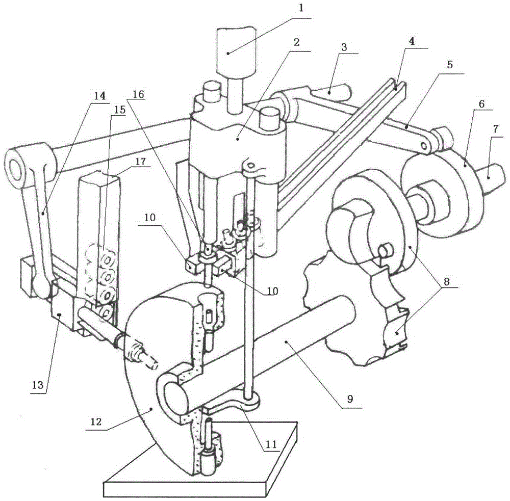
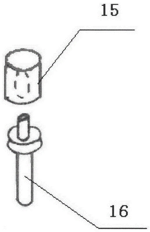
[0025] Such as figure 1 As shown, when a batch of plastic sleeves 15 and the stepped shaft 16 need to be press-fitted with a certain pressure, the plastic sleeves 15 can be placed on the slope slideway ( figure 1 Not shown in), the plastic sleeve 15 will slide into the square container 17 along the ramp slide. Place the stepped shaft 16 in the chute 4 in advance, the chute 4 is placed obliquely, the angle between the chute 4 and the horizontal plane is 25 degrees to 35 degrees, the stepped shaft 16 can continuously slide to the bottom of the chute 4, which can make the production continuous to automate. Now turn on the motor (not shown) to drive the camshaft 7, the camshaft 7 drives the cam 6 and the sheave mechanism 8, the sheave mechanism 8 drives the main shaft 9, the main shaft 9 drives the indexing dial 12 to rotate intermittently, and the cam 6 promotes the continuous Bar 5, connecting rod 5 drive rotating shaft 3, and rotating shaft 3 drives pusher 14, and pusher 14 p...
PUM
Abstract
The invention relates to an assembling device of mechanical parts and in particular relates to an automated mechanical device with matched shaft and sleeve. The automated mechanical device is composed of a pneumatic device, a pressure block, a rotating shaft, a sliding groove, a connecting rod, a cam, a cam shaft, a grooved wheel mechanism, a main shaft, a spring clamping jaw, a material pushing plate and the like; the grooved wheel mechanism is arranged on the main shaft and the cam shaft, the grooved wheel mechanism is connected with the main shaft by a general flat key, an indexing turn plate is arranged on the main shaft, the spring clamping jaw is arranged right above the indexing turn plate, the spring clamping jaw is arranged at the tail end of the sliding groove and is positioned right below the pressure block, a stepped shaft is arranged in the sliding groove, the pneumatic device and the pressure block are arranged above the sliding groove, and the sliding groove is arranged obliquely. According to the automated mechanical device, the manual labor intensity for assembling the shaft and the sleeve can be alleviated greatly, the working time is saved, and meanwhile, the labor productivity can be improved greatly. The s automated mechanical device has the advantages of exquisite structure, high automation degree, accurate transferring position, consistent pressure and high assembling precision, and the parts requiring interference fit can be assembled rapidly.
Description
technical field [0001] The invention relates to an assembly device of mechanical parts, in particular to an automatic mechanical device in which a shaft and a sleeve cooperate. Background technique [0002] In current industrial enterprises, such work is often encountered. The fit between the shaft and the sleeve is an interference fit. If it is manual assembly, it must be beaten with a hammer to beat the shaft or the sleeve so that they are tightly assembled. Such work is relatively heavy and is usually manually operated, which is difficult for continuous production. It is very wasteful of manpower, and the efficiency is low. Manually doing certain repetitive tasks for a long time is prone to fatigue. It is very headache when encountering such work. In large-scale machinery factories, there is also a hydraulic method to compress the shaft and the sleeve, but the use of hydraulic devices often requires a large investment and high cost, which is difficult for small enterpris...
Claims
Application Information
Patent Timeline
Application Date:The date an application was filed.
Publication Date:The date a patent or application was officially published.
First Publication Date:The earliest publication date of a patent with the same application number.
Issue Date:Publication date of the patent grant document.
PCT Entry Date:The Entry date of PCT National Phase.
Estimated Expiry Date:The statutory expiry date of a patent right according to the Patent Law, and it is the longest term of protection that the patent right can achieve without the termination of the patent right due to other reasons(Term extension factor has been taken into account ).
Invalid Date:Actual expiry date is based on effective date or publication date of legal transaction data of invalid patent.