
Method and device for switching a contactor

A technology of contactor and selection scheme, which is applied in the direction of electrical components, electric switches, circuits, etc., can solve the problems of uneven corrosion level, contactor service life limit, contact material thickness reduction, etc., and achieve the effect of increasing service life

Active Publication Date: 2015-05-20
ABB (SCHWEIZ) AG
View PDF7 Cites 2 Cited by
  • Summary
  • Abstract
  • Description
  • Claims
  • Application Information

AI Technical Summary

Problems solved by technology

Therefore, the thickness of the contact material of the affected contacts may decrease more rapidly
This results in different / uneven corrosion levels for different contacts
This means that the service life of the contactor is limited by which contact fails first

Method used


Image

  • Method and device for switching a contactor
  • Method and device for switching a contactor
  • Method and device for switching a contactor

Examples


Embodiment Construction

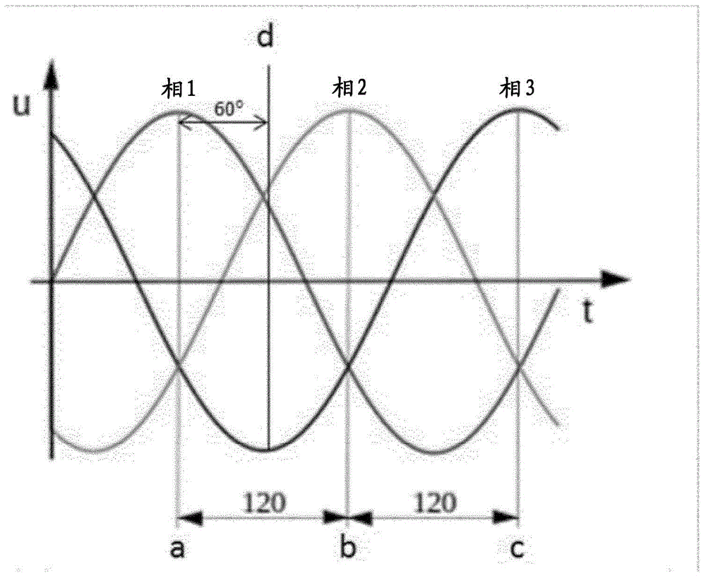
[0028] Figure 4a A low voltage contactor 1 according to an embodiment of the invention is shown. The low-voltage contactor 1 is used to connect the electric load 2 to a three-phase L 1 , L 2 , L 3 or disconnected from the main electrical network of the electrical load 2 in this example the engine.

[0029] The contactor 1 consists of a three-phase L connected to the mains network 1 , L 2 , L 3 Three main contacts 12 in each phase, an actuating unit comprising a coil 10, a fixed magnetic core 16 and a movable iron core 14, electronics for controlling the voltage / power supplied to the coil 10 control circuit 20. Each main contact includes a fixed contact and a movable contact connected to the movable iron core 14 . The coil 10, the fixed magnetic core 16 and the movable iron core 14 are arranged for actuating the main contacts 12, and thus for connecting and disconnecting operations.

[0030] In this example, the control voltage for the electronic control circuit consi...


PUM


Abstract

A low voltage contactor for connecting and disconnecting a three-phase load to an electric power including a coil, main contacts operated by the coil and an electronic control circuit for controlling voltage supplied to the coil. The electronic control circuit includes a pre-arranged time point selection scheme and is further adapted to select a time point from the pre-arranged time point selection scheme as a time delay, and initiate an instant opening command based on the selected time point.

Description

technical field [0001] The invention relates to a method and a device for switching a low-voltage contactor for operating a three-phase load, wherein said contactor comprises an actuating unit with a coil, main contacts operated by the coil and means for controlling the voltage supplied to the coil electronic circuit. In particular, the invention relates to initiating switching commands when controlling coils. Low voltage is usually limited to a range up to 1000V AC. Background technique [0002] A contactor is an electrically controlled switching device used to switch electrical power or control circuits of electrical loads connected to the circuit. The electrical load may be a three-phase load. In order to connect such an electrical load, the contactor comprises a contact unit comprising three main contacts and an actuation unit, the main contacts being configured to connect to or disconnect the load from the main electrical network , the actuating unit includes a coil...

Claims


Application Information

Patent Timeline
Patent Type & Authority Applications(China)
IPC IPC(8): H01H9/56
CPCH01H9/563
Inventor G·约翰森M·约翰森E·约翰森
Owner ABB (SCHWEIZ) AG
Learn More