
Image denoising method and terminal

An image noise reduction and noise reduction technology, applied in the field of image processing, can solve problems such as high algorithm complexity, low efficiency, and small amount of calculation

Active Publication Date: 2015-05-20
HUAWEI DEVICE CO LTD
View PDF6 Cites 10 Cited by
  • Summary
  • Abstract
  • Description
  • Claims
  • Application Information

AI Technical Summary

Problems solved by technology

[0003] The window filtering method that has nothing to do with the image content has a small amount of calculation, but the details of the image are seriously lost; the Non-local Means algorithm based on the similarity analysis of the image structure performs well in detail preservation and color protection, but the algorithm complexity is high. low efficiency

Method used


Image

  • Image denoising method and terminal
  • Image denoising method and terminal
  • Image denoising method and terminal

Examples


Embodiment 1

[0089] Such as figure 1 As shown, in an embodiment of a method for image noise reduction provided by the present invention, the method may include the following steps:

[0090] 101: Obtain image data of an image;

[0091] 102: Perform wavelet decomposition on at least one of the three components of the luminance component y, chrominance components u and v of the image data, to obtain high-frequency wavelet coefficients and low-frequency wavelet coefficients of each component;

[0092] 103: Perform recursive denoising on the low-frequency wavelet coefficients of each component to obtain the denoised low-frequency wavelet coefficients of each component;

[0093]104: Perform wavelet reconstruction according to the high-frequency wavelet coefficient of each component and the low-frequency wavelet coefficient after noise reduction of each component, to obtain at least one component after noise reduction;

[0094] 105: When the at least one component after the noise reduction is t...

Embodiment 2

[0099] With reference to Embodiment 1, in another embodiment of a method for image noise reduction provided by the present invention, as figure 2 As shown, before step 104, it may also include:

[0100] 1031: Perform an attenuation function based on edge information to denoise the high-frequency wavelet coefficients of each component;

[0101] The attenuation function denoising based on edge information for the high-frequency wavelet coefficients of each component includes:

[0102] According to the following formula, the high-frequency wavelet coefficients of each component are denoised,

[0103] y=αx+(1-α)h(x), where α is a parameter related to edge strength and h(x) is a decay function with respect to x.

[0104] In this implementation, the step 104 is specifically 104': performing wavelet reconstruction according to the high-frequency wavelet coefficients of each component after noise reduction and the low-frequency wavelet coefficients of each component after noise red...

Embodiment 3

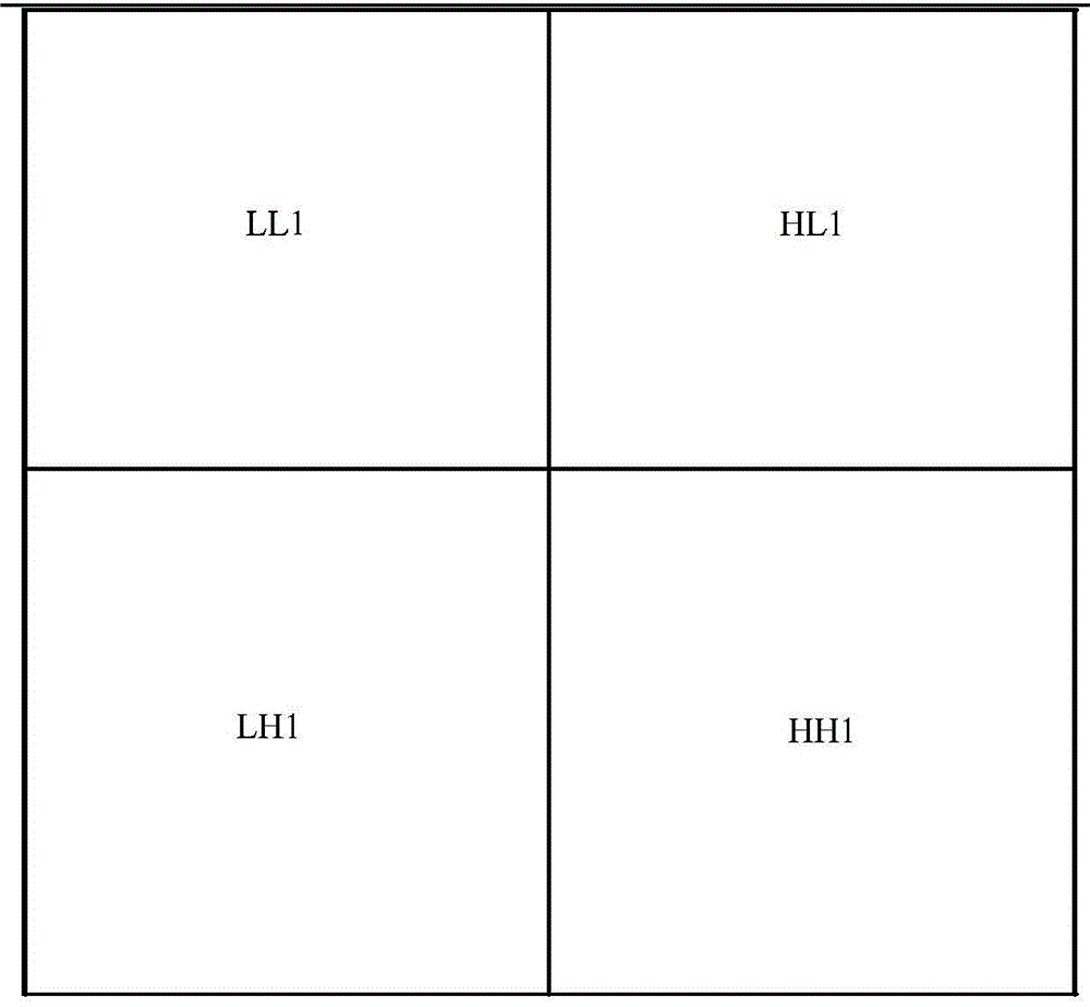
[0108] With reference to Embodiment 1, in another embodiment of the method for image noise reduction provided by the present invention, the step 102 may include: three luminance components y, chrominance components u and v of the image data At least one of the components is decomposed by n-layer wavelet to obtain n-layer high-frequency wavelet coefficients and n-layer low-frequency wavelet coefficients of each component, where n≥2, n is an integer.

[0109] Each image or photo can have three components of y, u, and v. Denoising the y component of the luminance component can mainly remove the luminance noise existing in the image; denoising the u and v components of the chroma component, It can mainly remove the color noise present in the image. Specifically, which components are denoised may be selected according to the type of noise existing in the image. One or more layers of wavelet decomposition can be performed on at least one of the three components of y, u, and v of th...


PUM


Abstract

Disclosed are a method and a terminal used for image noise reduction, wherein the method comprises: obtaining image data of an image; performing wavelet decomposition on at least one component of three components of luminance component y and chrominance components u and v in the image data to obtain a high frequency wavelet coefficient and a low frequency wavelet coefficient of each component; performing recursive noise reduction on the low frequency wavelet coefficient of the each component in at least one direction to obtain a low frequency wavelet coefficient after the noise reduction of the each component; performing wavelet reconstruction based on the high frequency wavelet coefficient of the each component and the low frequency wavelet coefficient after the noise reduction of the each component to obtain at least one component after the noise reduction; when the at least one component after the noise reduction comprises three components, combining the three components after the noise reduction to obtain image data after the noise reduction; and when the at least one component after the noise reduction comprises one or two components, combining the at least one component after the noise reduction with other components in the three components to obtain the image data after the noise reduction.

Description

technical field [0001] The invention relates to the field of image processing, in particular to a method and terminal for image noise reduction. Background technique [0002] In order to solve the problem of image noise, many image noise reduction algorithms have appeared in the industry, such as: window filtering method that has nothing to do with image content, Non-local Means (non-local mean) algorithm based on image structure similarity analysis, etc. [0003] The window filtering method that has nothing to do with the image content has a small amount of calculation, but the details of the image are seriously lost; the Non-local Means algorithm based on the similarity analysis of the image structure performs well in detail preservation and color protection, but the algorithm complexity is high. low efficiency. The contradiction between noise reduction effect and efficiency is even more prominent. Contents of the invention [0004] Embodiments of the present invention...

Claims


Application Information

Patent Timeline
Patent Type & Authority Applications(China)
IPC IPC(8): H04N5/21G06T5/00
CPCG06T5/10G06T2207/10024G06T2207/20064G06T5/20G06T2207/20016G06T2207/20192G06T5/70
Inventor 朱聪超罗巍杨小伟邓斌
Owner HUAWEI DEVICE CO LTD
Learn More