
Motor noise reduction structure of vacuum cleaner and vacuum cleaner

A vacuum cleaner and noise reduction technology, which is applied to the motor noise reduction structure and the field of vacuum cleaners, can solve the problems of weak deformation and reset ability of the compression spring, poor noise reduction effect, etc., and achieves strong reset ability, good noise reduction effect, and suppression of circumferential vibration. Effect

Active Publication Date: 2018-05-29
KINGCLEAN ELECTRIC
View PDF6 Cites 0 Cited by
  • Summary
  • Abstract
  • Description
  • Claims
  • Application Information

AI Technical Summary

Problems solved by technology

In this patented technology, a compression spring is used to support the motor, so that under normal working conditions, the compression spring is compressed due to the gravity of the motor. However, when the motor rotates, there will be a force of circumferential rotation, and the main elasticity of the compression spring is The deformation direction is along the direction of gravity. When there is a force of circumferential rotation, the compression spring will be subjected to a force perpendicular to the direction of gravity, so that the compression spring will be deformed due to the influence of the circumferential force. The deformation reset ability is weak, so that the motor will oscillate in the circumferential direction under the influence of the circumferential force, resulting in poor overall noise reduction effect

Method used


Image

  • Motor noise reduction structure of vacuum cleaner and vacuum cleaner

Examples


Embodiment Construction

[0021] In order to enable those skilled in the art to better understand the technical solutions in the present application, the technical solutions in the embodiments of the present application will be clearly and completely described below in conjunction with the drawings in the embodiments of the present application. Obviously, the described The embodiments are only some of the embodiments of the present application, but not all of them. Based on the embodiments in this application, all other embodiments obtained by persons of ordinary skill in the art without making creative efforts shall fall within the protection scope of the present invention.

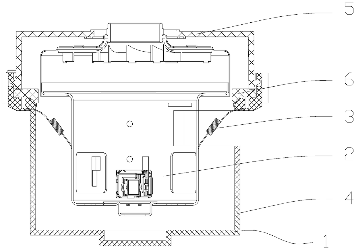
[0022] Please refer to figure 1 , the motor noise reduction structure of the vacuum cleaner provided in one embodiment of the present application is shown in the figure, the noise reduction structure includes: a mounting part, which can install the motor 2 on the vacuum cleaner; An elastic element 3 for applying tension, one end...


PUM


Abstract

The present application discloses a motor noise reduction structure of a vacuum cleaner and the vacuum cleaner. The noise reduction structure includes: a mounting part, which can install the motor on the vacuum cleaner; an elastic element that applies tension to the motor, and the elastic element One end is connected with the installation part, and the other end is connected with the motor; the pulling force can offset the gravity of the motor. The number of the elastic elements is at least two. The elastic elements are evenly distributed in the circumferential direction of the motor. The angle between the direction of the pulling force and the horizontal plane is 10°-85°. The installation part includes a motor cover. The motor cover includes a motor inner cover and a motor outer cover, and the motor outer cover and the motor inner cover form a storage space for accommodating the motor; the elastic element is connected to the motor outer cover or the motor inner cover. The lower part of the motor is suspended in the motor cover. The elastic element is a tension spring. The motor noise reduction structure of the vacuum cleaner and the vacuum cleaner of the present application can achieve a better motor noise reduction effect.

Description

technical field [0001] The present application relates to the field of cleaning equipment, in particular to a motor noise reduction structure of a vacuum cleaner and the vacuum cleaner. Background technique [0002] With the development of society and the continuous improvement of people's living standards, vacuum cleaners have been used in more and more families as a household cleaning device. A vacuum cleaner is an electrical appliance that uses a motor to generate negative air pressure in a sealed housing to suck in dust or garbage. The main function of the current vacuum cleaner is to recycle and clean the dust and garbage on the floor, carpet, etc. in the home. [0003] With the development of technology, the functions of vacuum cleaners are constantly improving, and at the same time, the motor power of vacuum cleaners is also gradually increasing. Since the low-frequency noise of the vacuum cleaner mainly comes from the vibration during the rotation of the motor, as t...

Claims


Application Information

Patent Timeline
Patent Type & Authority Patents(China)
IPC IPC(8): H02K5/24A47L9/28
CPCH02K5/24A47L9/0081A47L9/22
Inventor 倪祖根
Owner KINGCLEAN ELECTRIC
Learn More