


Quick Research
Generate reliable direction feasibility study reports for your R&D in just a few steps.

Technical Q&A
Discover and master advanced knowledge NOW. Basics, ideas, possibilities, all at once.

Find Solutions
As an expert in R&D theories, this can generate solutions to your technical problems instantly.

Evaluate Feasibility
Analyze your overall solution with one click, know your potential R&D risks in advance.

Monitor Landscape
Get weekly tech updates, stay abreast of the latest tech innovations and key insights.
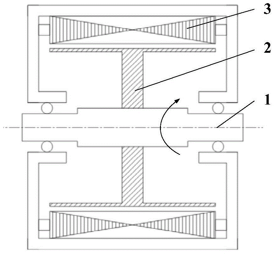
Induction rotor structure of a high-power and high-speed electromagnetic eddy current dynamometer
A technology of electromagnetic eddy current and rotor structure, applied in the direction of magnetic circuit shape/style/structure, instrument, power measurement, etc. Problems such as the maximum speed of the eddy current dynamometer, to achieve the effect of increasing the rated absorbed power, large braking torque, and expanding the area of the sensing area
- Summary
- Abstract
- Description
- Claims
- Application Information
AI Technical Summary
Problems solved by technology
Method used
Image

Examples
Embodiment approach
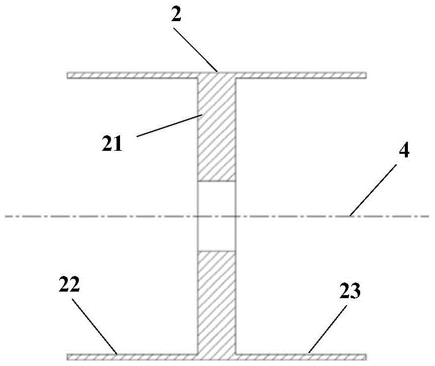
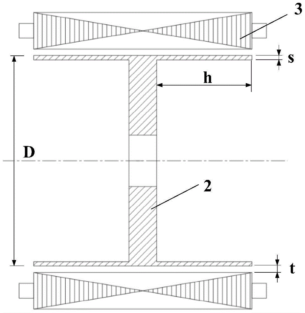
[0019] As an implementation, for example, the wall thickness of the double-cup induction rotor cup is selected as s=6mm; the material of the induction rotor is TC11, and its allowable stress [σ]=6.64×10 8 Pa, density ρ=4.48×10 3 kg / m 3 , Resistivity γ=1.85×10 -6 Ω·m; the distance between the outer wall of the double-cup induction rotor and the inner wall of the stator armature core t = 3mm; coefficient A = 20. The design requires the maximum excitation current I = 12A, the maximum speed n max =18000rpm, rated absorbed power P t ≥3000kW.
[0020] by relation The maximum diameter D allowed by the outer wall of the double-cup induction rotor can be calculated max =379.5mm; by relation It can be calculated that the cup depth h of the double-cup induction rotor is greater than or equal to 107mm. As an implementation manner, the diameter of the outer wall of the double-cup induction rotor is D=300 mm, and the depth of the cup body h=150 mm.
[0021] The strength check res...
PUM
| Property | Measurement | Unit |
|---|---|---|
| thickness | aaaaa | aaaaa |
| yield strength | aaaaa | aaaaa |
| density | aaaaa | aaaaa |
Abstract
Description
Claims
Application Information
 - R&D Engineer
- R&D Manager
- IP Professional
- Industry Leading Data Capabilities
- Powerful AI technology
- Patent DNA Extraction
Browse by: Latest US Patents, China's latest patents, Technical Efficacy Thesaurus, Application Domain, Technology Topic, Popular Technical Reports.
© 2024 PatSnap. All rights reserved.Legal|Privacy policy|Modern Slavery Act Transparency Statement|Sitemap|About US| Contact US: help@patsnap.com