
Electronic lock

An electronic lock and lock body technology, applied in the field of electronic locks, can solve problems such as difficult assembly and maintenance, complex structure, etc.

Inactive Publication Date: 2015-05-20
温州市霸力锁具有限公司
View PDF6 Cites 5 Cited by
  • Summary
  • Abstract
  • Description
  • Claims
  • Application Information

AI Technical Summary

Problems solved by technology

[0005] The working principle of the above-mentioned patent application documents: when locking the door, the lock tongue can be extended out of the lock body by turning the handle counterclockwise; The bolt assembly and the bolt assembly make the bolt move into the lock body, but such a structure is too complicated and difficult to assemble and maintain

Method used


Image

  • Electronic lock
  • Electronic lock
  • Electronic lock

Examples


Embodiment Construction

[0035] The specific implementation manners of the present invention will be further described in detail below in conjunction with the accompanying drawings and embodiments. The following examples are used to illustrate the present invention, but are not intended to limit the scope of the present invention.

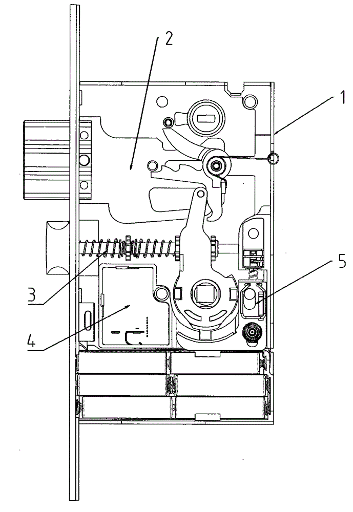
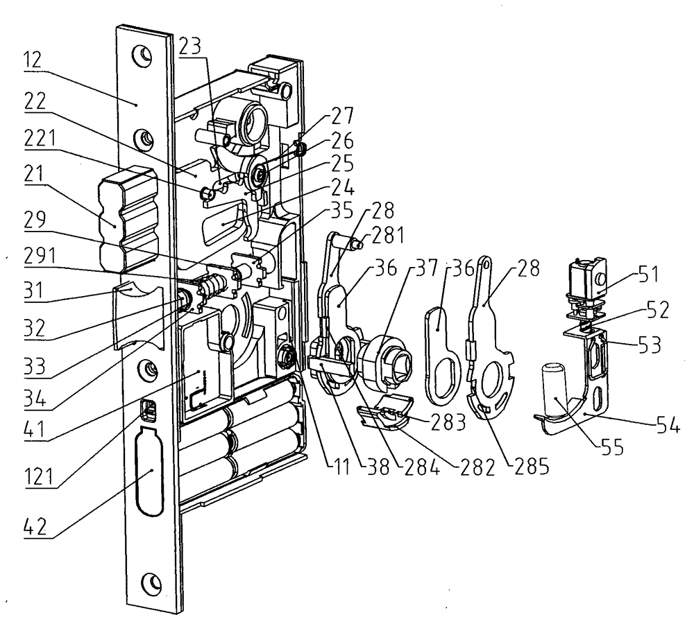
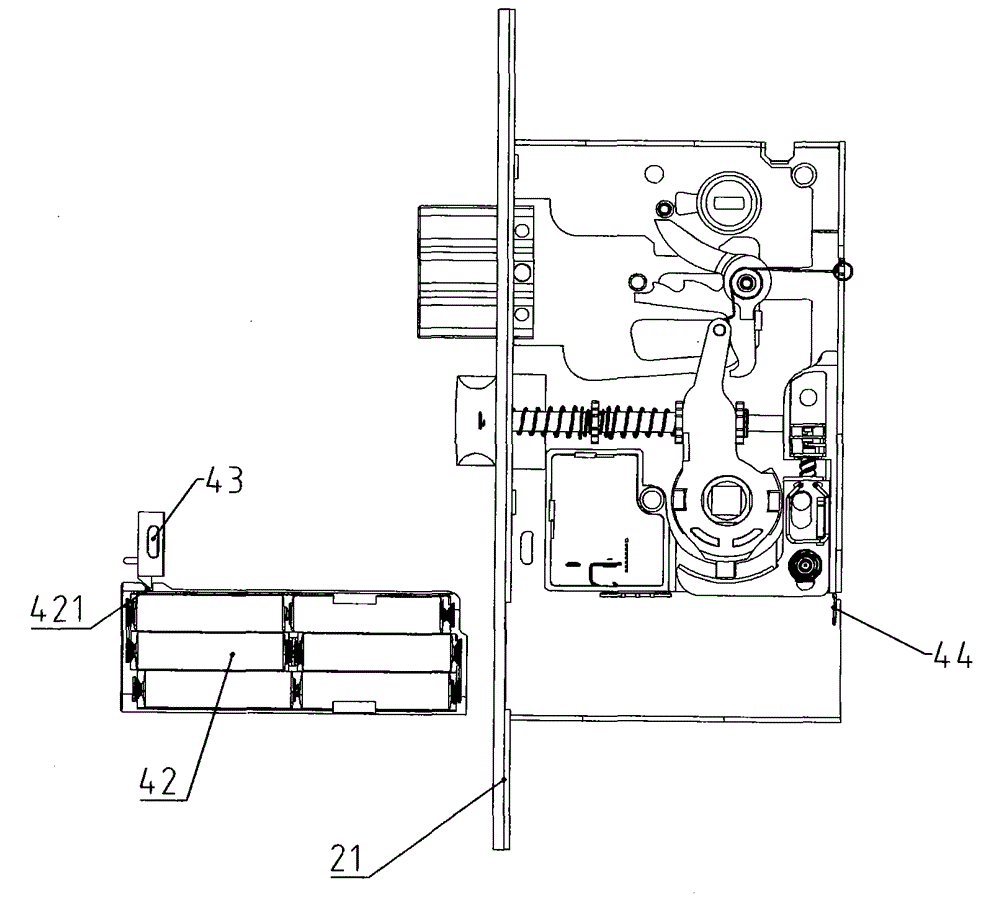
[0036] combine Figure 1 to Figure 4-8 As shown, an electronic lock includes a lock body 1, a square tongue assembly 2, a latch bolt assembly 3 and a circuit control assembly 4 are arranged in the lock body 1, and the latch bolt assembly 3 includes a latch bolt 31, a latch bolt pick 36 and a latch bolt The rotor seat 37, the oblique tongue rotor seat 37 is provided with a handle through hole 371 for installing the handle (omitted in the accompanying drawings), the square tongue assembly 2 includes the square tongue 21 and the drive square tongue 21 to make it extend relative to the lock body 1 The square tongue plectrum 28 that goes out and stretches in, the side portion ...


PUM


Abstract

The invention provides an electronic lock. The electronic lock comprises a lock body. A dead bolt assembly, a latch bolt assembly and a circuit control assembly are arranged in the lock body. The latch bolt assembly comprises a latch bolt, a latch bolt deflecting plate and a latch bolt rotor base. The dead bolt assembly comprises a dead bolt and a dead bolt deflecting plate used for driving the dead bolt to stretch out of and stretch into the lock body. The dead bolt deflecting plate and the latch bolt deflecting plate are connected to the latch bolt rotor base in a sleeving mode. The dead bolt deflecting plate is arranged on the latch bolt rotor base in a linkage mode, and the latch bolt deflecting plate is movably arranged on the latch bolt rotor base. The dead bolt deflecting plate is provided with a linkage protruding block extending towards the latch bolt deflecting plate. The latch bolt deflecting plate abuts against the linkage protruding block to drive the dead bolt deflecting plate and then lock the dead bolt when swinging anticlockwise. The lock body further comprises a linkage plug pin assembly which is used for achieving disengagement and engagement between the dead bolt deflecting plate and latch bolt deflecting plate. The electronic lock is simpler in structure and more convenient to open and close.

Description

technical field [0001] The invention relates to a lock, in particular to an electronic lock. Background technique [0002] At present, door locks sold on the market can be roughly divided into two types, namely mechanical locks and electronic locks. The so-called mechanical lock refers to the mechanical connection between the various components in the entire lock body. This type of door lock is widely used in daily life. 1. The dial between the outer paddles; although the mechanical lock does not need to be powered, its disadvantage is that it is poor in safety, mainly because the key to open the mechanical lock is easy to copy. Therefore, existing mechanical lock still can't satisfy the needs of people's life, needs to be improved urgently. The electronic lock controls the circuit or chip work (access control system) by password input, thereby controlling the closing of the mechanical switch and completing the electronic product of unlocking and locking tasks. However, af...

Claims


Application Information

Patent Timeline
IPC IPC(8): E05B47/00E05B15/10E05B15/12E05B15/00E05B63/14
Inventor 唐志雄
Owner 温州市霸力锁具有限公司
Learn More