
Rainwater particle separation and regulation and storage system

A particle separation and rainwater technology, applied in waterway systems, water supply devices, drainage structures, etc., can solve the problems of inability to rotate the inclined plate, soil erosion, fixed treatment capacity, etc., to increase sedimentation efficiency, prevent floods, and simple structure. Effect

Active Publication Date: 2015-05-20
WUHAN SHENGYU DRAINING SYST
View PDF8 Cites 14 Cited by
  • Summary
  • Abstract
  • Description
  • Claims
  • Application Information

AI Technical Summary

Problems solved by technology

In addition, direct discharge of these sediment and other particles into natural water will cause soil erosion
[0003] The Chinese invention patent titled "A Hydraulic Particle Separator for Rainwater Pretreatment" with the application number 201210447222.9 provides a rainwater particle treatment device, which is equipped with a sloping plate sedimentation tank to treat the particles in the water body Effective settlement, but the inclined plate of the device cannot be rotated, the processing capacity is fixed, and cannot be adjusted according to the water volume
In addition, the rainwater in this device directly enters the sedimentation tank without pretreatment and sedimentation process, which will lead to the treatment of subsequent processes
The flushing device of this device directly flushes particulate matter such as sediment into the sewage pool, but the sewage pool is connected to the rainwater inlet, which will increase the particulate matter content of the rainwater, and even block the pipeline in severe cases

Method used


Image

  • Rainwater particle separation and regulation and storage system
  • Rainwater particle separation and regulation and storage system

Examples


Embodiment Construction

[0022] The present invention will be further described in detail below in conjunction with the accompanying drawings and specific embodiments.

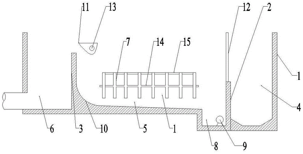
[0023] Such as Figure 1~2 , a system for separating and regulating rainwater particles, comprising a regulating pond 1, and the regulating pond 1 is composed of three interconnected ponds, (such as figure 1 As shown, the left and right direction of the drawing is the left and right direction) from right to left are the rainwater channel 4, the sedimentation tank 5 and the drainage tank 6, and the separation between the three pools is two first overflows that are parallel to each other and arranged at intervals. The plate 2 and the second overflow plate 3, wherein the upper end of the first overflow plate 2 is equipped with a grid 12, the main function of the grid 12 is to isolate the large impurities in the rainwater, and avoid entering the subsequent treatment stage.

[0024] The upper end of the second overflow plate 3 is higher t...


PUM


Abstract

The invention relates to the field of city rainfall regulation and storage control, in particular to a rainwater particle separation and regulation and storage system. The rainwater particle separation and regulation and storage system comprises a regulation tank. A first overflow plate and a second overflow plate are parallelly disposed in the regulation tank at intervals. The first overflow plate and the second overflow plate cut the regulation tank into a rainwater channel on the right of the first overflow plate, a sedimentation tank between the first overflow plate and the second overflow plate and a draining tank on the left of the second overflow plate. A plurality of sedimentation plates made of plastic plates are parallelly disposed in the sedimentation tank. The inclination angles of the sedimentation plates are changed through hydraulic power. A sediment washing device and a sediment accumulation tank for collecting particles such as sediment are further disposed in the sedimentation tank. The sediment accumulation tank is located at a low position at the bottom of the sedimentation tank. A submersible sewage pump for discharging the particles such as the sediment is disposed in the sediment accumulation tank. The rainwater particle separation and regulation and storage system is simple in structure, convenient to operate, high in automation level and worthy of popularization.

Description

technical field [0001] The invention relates to the field of urban rainwater regulation and storage control, in particular to a rainwater particle separation and regulation and storage system. Background technique [0002] In recent years, many large cities have experienced heavy rainstorms, and the amount of precipitation far exceeds the design capacity of existing sewage treatment plants. The rainwater that cannot be treated is generally discharged into natural water bodies through rainwater pipes. However, direct discharge of rainwater into natural water bodies will cause great damage to natural water bodies, which are specifically reflected in the following aspects: 1. The large amount of rainwater discharge will increase the hydraulic load of natural water bodies; 3. Rainwater will bring a large amount of sediment and other substances on the ground into the natural water body, seriously polluting the natural water body. Sediment and other particulate matter affect the ...

Claims


Application Information

Patent Timeline
Patent Type & Authority Applications(China)
IPC IPC(8): E03F5/10B01D21/02
CPCB01D21/02E03F5/10
Inventor 李习洪周超
Owner WUHAN SHENGYU DRAINING SYST
Learn More