Weft yarn detector for air-jet looms

A technology of air-jet looms and detectors, which is applied to looms, auxiliary weaving equipment, textiles, etc., and can solve problems such as difficult inspection of weft yarns by stroboscopes

Active Publication Date: 2016-05-25
TOYOTA IND CORP
View PDF8 Cites 0 Cited by
  • Summary
  • Abstract
  • Description
  • Claims
  • Application Information

AI Technical Summary

Problems solved by technology

However, in fabric constructions where the top warp yarns are continuous (such as satin weave), it is difficult in some cases to use a stroboscope to check the state of the weft yarns in the warp shed

Method used


Image

  • Weft yarn detector for air-jet looms
  • Weft yarn detector for air-jet looms
  • Weft yarn detector for air-jet looms

Examples


Embodiment Construction

[0018] will now refer to Figures 1 to 5 An embodiment of the present invention will be described.

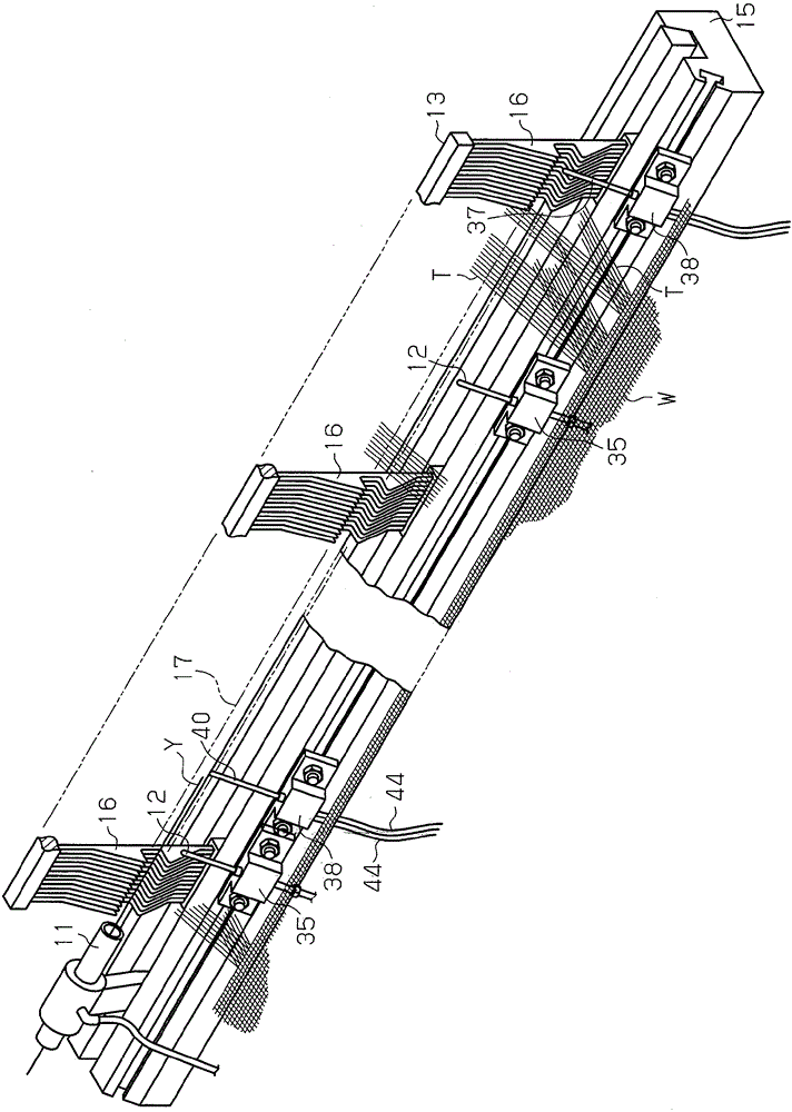
[0019] Such as figure 1 and 2 As shown in , the air jet loom includes a main nozzle 11 used in weft insertion, an auxiliary nozzle 12 used in weft insertion, a reed 13, and a weft yarn measuring and storing device 14 of winding type. Such as figure 2 As shown in , the main nozzle 11 , the auxiliary nozzle 12 and the reed 13 are fixed to the sley 15 . The reed 13 comprises a plurality of reed teeth 16 arranged in the weft insertion direction. Each reed tooth 16 has a guide notch 16a ( image 3 shown in ). The guide recesses 16 a of the reed teeth 16 form passages or reed passages 17 in the reed 13 .

[0020] Such as figure 1 As shown in , the main nozzle 11 is connected to a sump 19 for the main nozzle 11 via a pipeline. The main nozzle tank 19 is connected to the source pressure tank 18 . The solenoid valve 20 is provided between the main nozzle 11 and the main noz...


PUM


Abstract

A weft yarn detector is adapted to be used in an air-jet loom, in which weft insertion of a weft yarn through a reed passage is performed by air jet from a main nozzle and auxiliary nozzles. An optical sensor for detecting the extent of slack of the weft yarn is located in the reed passage at a position close to the main nozzle.

Description

technical field [0001] The present invention relates to a weft yarn detector for an air-jet loom. More specifically, the present invention relates to a weft yarn detector for an air-jet loom that performs weft insertion through a passage in a reed by means of blowing air from a main nozzle and an auxiliary nozzle. Background technique [0002] In such air-jet looms, the state of the weft thread during weft insertion depends greatly on the pressure setting of the pressurized air. Conventionally, Japanese Laid-Open Patent Publication No. 4-241135 discloses a pressure control device for weft insertion in an air-jet loom, which can improve the consumption efficiency of discharged fluid while eliminating the weft yarn in the second half of weft insertion. slack and less mispicks in weft insertion. The control device detects the weft yarn development completion time in the device for measuring the weft yarn measurement and stores the weft yarn, and the weft yarn front arrival ti...

Claims


Application Information

Patent Timeline
Patent Type & Authority Patents(China)
IPC IPC(8): D03J1/04D03D47/30
CPCD03D47/30D03J1/04D03D47/3073D03D47/3093D03D51/34
Inventor 荒井隆二铃木藤雄牧野洋一
Owner TOYOTA IND CORP
Why Eureka
Try Eureka