
Control method of a serial printer, and serial printer

A control method and printer technology, applied to printing devices, printing, transfer materials, etc., can solve the problem of removing recording paper, etc., and achieve the effect of suppressing the contact of the printing head

Inactive Publication Date: 2015-05-20
SEIKO EPSON CORP
View PDF11 Cites 4 Cited by
  • Summary
  • Abstract
  • Description
  • Claims
  • Application Information

AI Technical Summary

Problems solved by technology

In this case, it may be difficult to remove the recording paper from the paper conveyance path due to the movement of the recording paper.

Method used


Image

  • Control method of a serial printer, and serial printer
  • Control method of a serial printer, and serial printer
  • Control method of a serial printer, and serial printer

Examples


Embodiment Construction

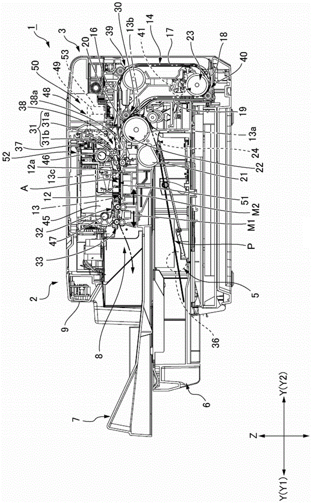
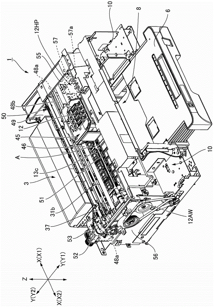
[0028] Hereinafter, a serial printer to which the present invention is applied will be described with reference to the drawings.

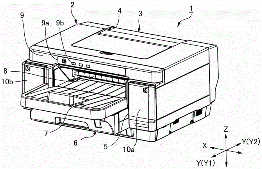
[0029] (the whole frame)

[0030] figure 1 It is an external perspective view of the serial printer according to this embodiment seen from the front. The serial printer 1 has a printer body 2 and a reversing unit 3 . The printer main body 2 has a rectangular parallelepiped shape that is long in the printer width direction X as a whole. The reversing unit 3 is attached to a recess 4 provided in the center portion of the rear surface of the printer main body 2 . The reversing unit 3 is a unit for reversing the front and back of the printing paper.

[0031] A paper feeding cassette mounting portion 5 is provided on the printer main body portion 2 . The paper feeding cassette mounting portion 5 opens toward the printer front Y1 (forward in the printer longitudinal direction Y) at the lower portion in the printer vertical direction Z of the front s...


PUM


Abstract

A control method of a serial printer enables easily removing the printing paper when a paper jam occurs, and can prevent or suppress damage to the printhead when removing the printing paper. A serial printer 1 conveys printing paper P by a conveyance mechanism 22 including a second paper feed roller pair 31 located upstream from the print position A in the first conveyance direction M1. If a paper jam of the printing paper P is detected when the printhead 12 is at a position opposite the horizontal conveyance path portion 13c of the paper conveyance path 13, conveyance of the printing paper P first stops, and the printhead 12 is then moved on the vertical axis Z away from the horizontal conveyance path portion 13c. Next, the printhead 12 is moved on the transverse axis X to a away position 12AW outside the horizontal conveyance path portion 13c, and nipping of the printing paper P by the second paper feed roller pair 31 is then released.

Description

technical field [0001] The present invention relates to a control method of a serial printer that retracts a print head when a recording paper jam occurs, and the serial printer. Background technique [0002] Patent Document 1 describes a printing apparatus that conveys recording paper along a paper conveyance path passing through a printing position of a print head, and performs printing on the recording paper at the printing position. In the printing device of Patent Document 1, the recording paper is conveyed by the conveying roller pair. The conveyance roller pair includes a conveyance roller to which the driving force of the conveyance motor is transmitted, and a driven roller driven by the conveyance roller. In addition, the print head is movable between a printing position and a retracted position away from the printing position. A link mechanism for moving the driven roller as the print head moves is provided between the print head and the driven roller. [0003] ...

Claims


Application Information

Patent Timeline
Patent Type & Authority Applications(China)
IPC IPC(8): B41J29/38B41J11/00
CPCB41J2/16511B41J2/1652B41J11/006B41J25/3088
Inventor 品川洋辉深泽弘保
Owner SEIKO EPSON CORP
Learn More