Quick-replacement fixture

A technology of quick-change fixtures and fixtures, which is applied in the direction of clamping, manufacturing tools, supports, etc., can solve the problem of inconvenient tool replacement on drilling machines, achieve the effects of reducing labor intensity, improving work efficiency, and increasing the speed of tool changing

Inactive Publication Date: 2015-05-20
成都液力机械有限公司
View PDF0 Cites 9 Cited by
  • Summary
  • Abstract
  • Description
  • Claims
  • Application Information

AI Technical Summary

Problems solved by technology

[0003] The invention solves the problem of inconvenient tool replacement on a drilling machine, and provides a quick-change tool that can quickly and easily replace tools, effectively reduce labor intensity, and improve work efficiency

Method used


Image

  • Quick-replacement fixture
  • Quick-replacement fixture

Examples


Embodiment Construction

[0010] The present invention will be further described below in conjunction with the accompanying drawings.

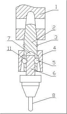
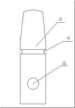
[0011] Such as figure 1 and 2 As shown, it is a quick-change clamp, which includes a clamp body 2, a clamp rod 6, a steel ball 5 and a locking sleeve 4. One end of the clamp body 2 is provided with a mounting hole 7, and the outer wall of the clamp body mounting hole 7 is provided with symmetrical Two ball sockets 10, the clamp rod 6 is set in the mounting hole 7 of the clamp body 2, the clamp rod 6 is provided with a locking groove 11, the locking sleeve 4 is set on the clamp body 2, and the inner surface of the locking sleeve 4 is With a conical surface with a certain inclination angle, the steel balls 5 are respectively installed in the two ball sockets 10, the steel balls 5 are stuck in the locking groove 11 of the clamp rod 6, and the inner surface of the locking sleeve 4 is pressed on the steel balls 5. An annular groove 9 is arranged on the fixture body 2, and...


PUM


Abstract

A quick-replacement fixture comprises a fixture body, a fixture rod, steel balls and a locking sleeve. An installation hole is formed in one end of the fixture body, and two ball sockets are symmetrically arranged on the outer wall of the installation hole of the fixture body. The fixture rod is arranged in the installation hole of the fixture body in a sleeved mode, and locking grooves are formed in the fixture rod. The fixture body is sleeved with the locking sleeve. The inner surface of the locking sleeve is a conical surface at a certain inclination angle, the steel balls are installed in the two ball sockets respectively and clamped in the locking grooves of the fixture rod, and the inner surface of the locking sleeve presses the steel balls. The quick-replacement fixture achieves quick and easy replacement of tools, effectively relieves labor intensity and improves working efficiency.

Description

technical field [0001] The invention relates to a machining fixture, in particular to a quick-change fixture used on a drilling machine. Background technique [0002] In the tool clamping method of the drilling machine, the structure in which the inner tapered hole of the main shaft of the drilling machine is matched with the outer tapered surface of the tool handle (or transition sleeve) is generally adopted. When changing the tool, it is necessary to insert the wedge iron into the dismounting hole on the main shaft of the drilling machine, and then knock the wedge iron with a hammer to remove the tool. When machining a part with various specifications of holes, frequent tool replacement will accompany the entire machining process, and the method of using a hammer to strike a wedge iron to change tools is time-consuming, laborious and noisy. Contents of the invention [0003] The invention solves the problem of inconvenient tool replacement on a drilling machine, and pro...

Claims


Application Information

Patent Timeline
Patent Type & Authority Applications(China)
IPC IPC(8): B23Q3/12
CPCB23Q3/12
Inventor 徐运福王强
Owner 成都液力机械有限公司
Why Eureka
Try Eureka