
Assembly mold for forklift fork frame main roller shaft

A technology for the fork frame and roller shaft, which is applied in the field of assembly molds for the main roller shaft of the forklift fork frame, can solve the problems of large shape and position tolerance, complex calibration process, and low production efficiency, and achieve high precision, low labor intensity, The effect of easy demoulding

Active Publication Date: 2016-04-20
ANHUI HELI CO LTD
View PDF6 Cites 0 Cited by
  • Summary
  • Abstract
  • Description
  • Claims
  • Application Information

AI Technical Summary

Problems solved by technology

[0004] In order to solve the problems existing in the assembly of the existing main roller shafts, such as large shape and position tolerances, complex calibration procedures, and low production efficiency, the present invention designs an assembly mold for the main roller shaft of a forklift fork frame.

Method used


Image

  • Assembly mold for forklift fork frame main roller shaft
  • Assembly mold for forklift fork frame main roller shaft
  • Assembly mold for forklift fork frame main roller shaft

Examples


Embodiment 1

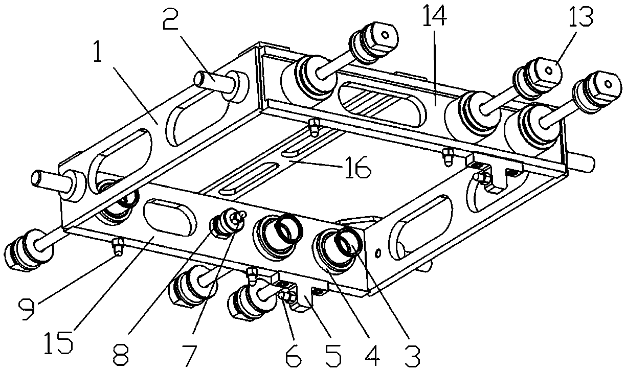
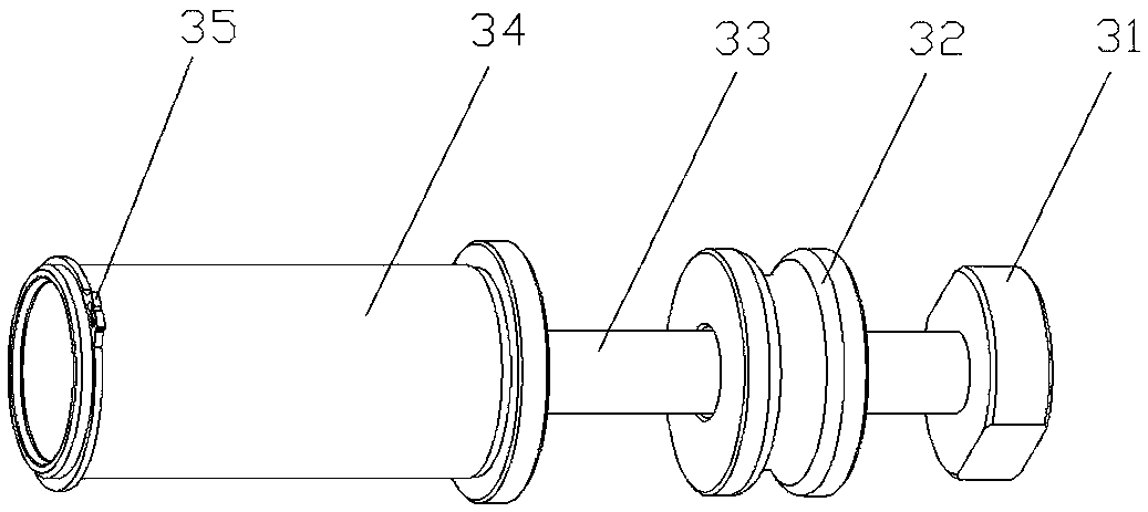
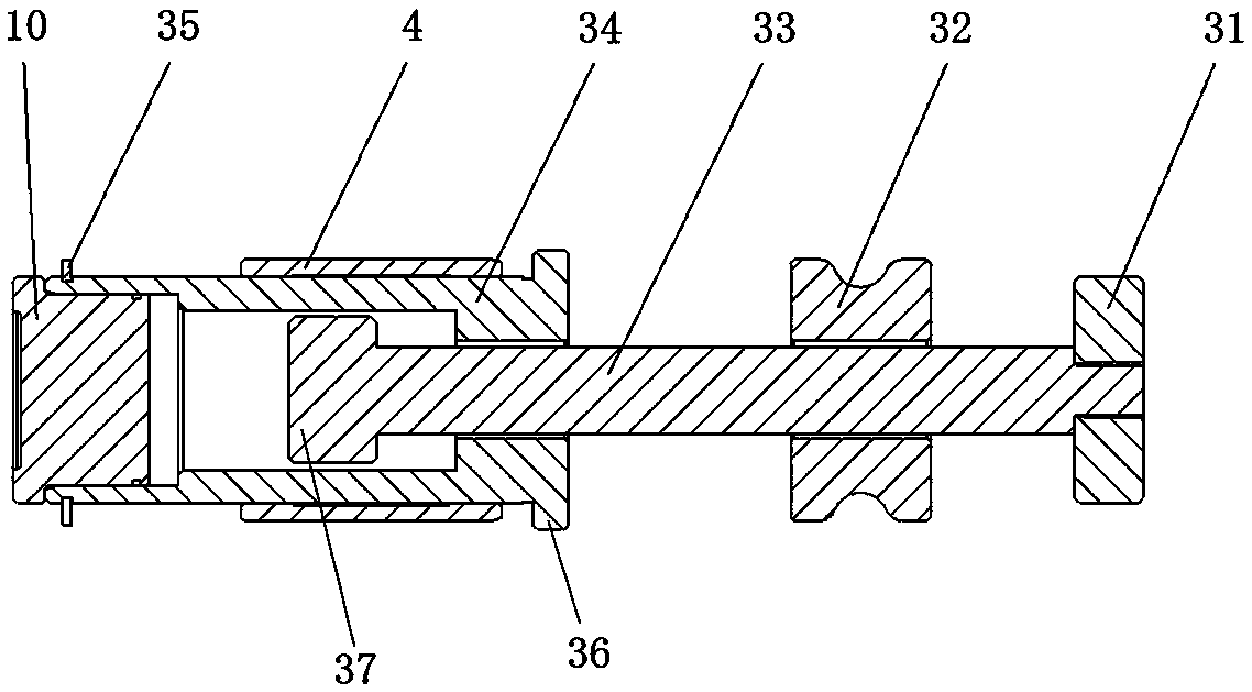
[0032] Example 1: see figure 1 , an assembly mold for the main roller shaft of a forklift fork frame, including a frame 1, a first positioning mechanism 3, and a second positioning mechanism 13;

[0033] The frame 1 is a rectangular frame formed by splicing four side panels;

[0034] The two opposite side plates of the frame 1 are respectively provided with more than two first positioning mechanisms 3 and more than two second positioning mechanisms 13, and the side plates of the frame 1 provided with the first positioning mechanisms 3 are the first side plates 15. The frame 1 side plate provided with the second positioning mechanism 13 is the second side plate 14; the two or more first positioning mechanisms 3 are arranged on the same level, and the first positioning mechanism 3 and the second positioning mechanism 13 are one One correspondence, and the first positioning mechanism 3 and the second positioning mechanism 13 are arranged symmetrically;

[0035] The first posi...

Embodiment 2

[0043] Example 2: The first side plate 15 is provided with three first positioning mechanisms 3 , and the three first positioning mechanisms 3 are set according to the installation position of the main roller shaft 10 , and the rest of the structure is the same as that of the first embodiment.

Embodiment 3

[0044] Example 3: The bottom surface of the first side plate 15 is provided with two third positioning pins 9, and the two third positioning pins 9 are located on the bottom surface of the first side plate 15 on one side of the step seat 5, and are connected with the second positioning pins 6. Two-dimensional positioning is formed, and all the other structures are the same as in Embodiment 1.

[0045] Concrete operation steps of the present invention are as follows:

[0046](1) see Figure 6 , the two vertical plates 11 are vertically arranged in the middle of the fork frame 12 as required, and the two vertical plates 11 are arranged symmetrically;

[0047] (2) see Figure 4 , Figure 5 Hold the handle 2 and place the present invention on the fork frame 12, so that the two vertical plates 11 are located on the frame 1, and the first side plate 15 and the second side plate 14 of the frame 1 are respectively parallel to the two vertical plates 11. The second positioning pi...


PUM


Abstract

It is used for the assembly mold of the main roller shaft of the forklift fork frame. The frame is a rectangular frame formed by splicing four side plates; two or more first positioning mechanisms, two or more The second positioning mechanism; the two or more first positioning mechanisms are arranged on the same horizontal plane, the first positioning mechanism corresponds to the second positioning mechanism one by one, and the first positioning mechanism and the second positioning mechanism are arranged symmetrically; The structure of the first positioning mechanism is the same as that of the second positioning mechanism; the first positioning mechanism is composed of a bushing, a sleeve, a sliding rod, a second stopper, a sliding block and a first retaining ring; the first side plate An adjustment seat is provided on the inner surface, the adjustment seat is arranged parallel to the sleeve and faces the middle of the frame, and the end of the adjustment seat is provided with a first positioning pin; the bottom surface of the first side plate and the bottom surface of the second side plate A pin assembly is arranged symmetrically; the pin assembly is composed of a step seat, a second positioning pin and a third positioning pin; the invention has a simple structure and is convenient to use.

Description

technical field [0001] The invention belongs to the field of mechanical tooling, and in particular relates to an assembly mold for the main roller shaft of a forklift fork frame. Background technique [0002] At present, there are 4 or 6 main roller shafts on the fork frame of a 1-3.5t internal combustion forklift and are assembled and welded with the fork frame. The symmetry and verticality also have precision control requirements. [0003] The existing main roller shaft and the part vertical plate in the fork frame are first assembled into a small assembly, and the small assembly is assembled and welded with the fork frame. This assembly method has the following disadvantages: (1). In the two assembly, the flatness and parallelism of the center line of the main roller shaft exceed the control requirements, and the out-of-tolerance problem needs to be solved by means of correction, and the correction process is complicated; The assembly of the fork frame is complex in ope...

Claims


Application Information

Patent Timeline
Patent Type & Authority Patents(China)
IPC IPC(8): B23K37/04
CPCB23K37/0443
Inventor 汪和平董艳平高全胜何振华徐洪俊刁伟
Owner ANHUI HELI CO LTD
Learn More